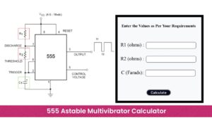
When designing a new electronic circuit with a 555 timer IC, this 555 Timer Calculator will allow you to calculate the output signal parameters. The same calculator tool allows you to select two different modes: astable and monostable.
555 Timer Calculator
555 Timer Calculator
Results:
You can select this mode using the dropdown option. To calculate the parameters of the output signal using astable mode; thus you need to select astable mode and enter resistor R1, R2, and capacitor C values and it will return a frequency, high time, low time, and duty cycle. In monostable, you must select the values of resistor R and capacitor C to get the pulse width. Key in your values and then press the “Calculate” button to see your results. You can also click the “Clear” button to reset all inputs and results.
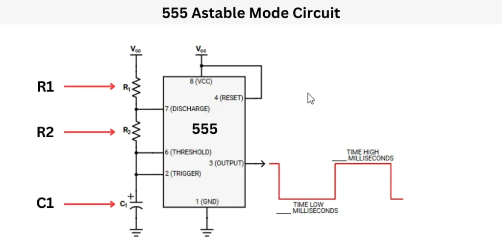
555 Astable Multivibrator Circuit
The astable multivibrator circuit, which uses the 555 IC, continuously switches the output signal to High and Low states. This process does not need an external trigger. The output signal will be in the square waveform.
The astable multivibrator circuit consists of a 555 Timer IC, Resistors R1 and R2, and a Capacitor C1. These two resistors and the capacitor values determine the frequency, High time, Low time, and also the duty cycle.
When the circuit is powered on, the capacitor charges through the resistors. When the charging capacitor reaches its certain voltage, then it will start to discharge. This charging and discharging process is repeated continuously. This creates a stable, automatic ON-OFF switching effect at the output pin.
The formula to calculate the frequency in “astable mode” is f = 1.44 / (R1 + 2R2) C1. This type of astable multivibrator circuit is commonly used for flashing LEDs, generating clock pulses, tone generation, and pulse width modulation (PWM).
555 Astable calculator Formula
- Frequency (f)= 1.44/(R1+2R2)XC1
- High Time (Thigh) = 0.639x (R1+R2)XC1
- LOW TIME (Tlow) = 0.693xR2xC1
- Duty Cycle (D%) = (Thigh/Thigh +Tlow)x 100
555 monostable multivibrator circuit

In this monostable multi-vibrator circuit the 555 timer IC single pulse for a specific period. This will be controlled by an external trigger switch. When the trigger switch is pressed the circuit starts to work.
The circuit consists of a 555 timer IC, a resistor (R1), and a capacitor (C1) which will determine the pulse width.
When a trigger pulse is applied, the output switches from LOW to HIGH for a fixed time, then automatically returns to LOW.
The pulse duration (T) is calculated by using this formula of T = 1.1 × R1 × C1
where R1 is in ohms and C1 is in farads. This type of monostable multivibrator circuit is used in timing applications such as delays, pulse generation, and touch switches.
555 Monostable Calculator Formula
Pulse width (Tpulse): Tpulse= 1.1 x R x C