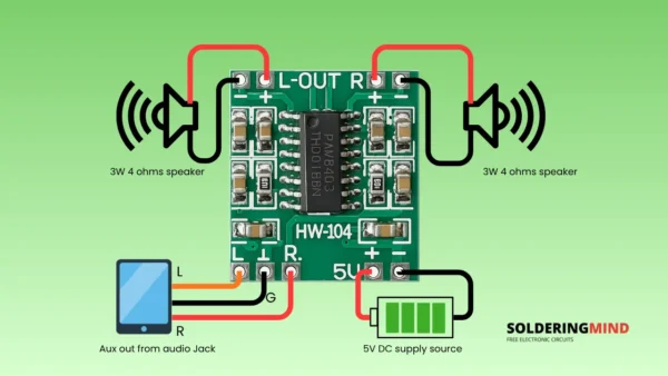
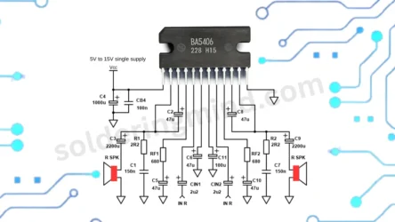
When a microphone is directly connected to the amplifier the sound may be very low. This happening due to the microphone is producing the electrical charge into very little of audio sounds. In this situation we need to add additional small Microphone preamplifier circuit board to boost or amplifying the audio comes from the microphone.
Microphone Preamplifier Circuit Diagram
Connections and Working of Circuit
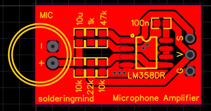
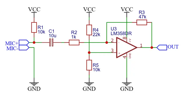
The circuit is a simple microphone preamplifier using anLM358 operational amplifier. A condenser microphone is connected at the left side of the circuit with its positive terminal connected to a 10kΩ resistor (R1) and it goes to VCC connection. The negative terminal connected to ground. A 10µF capacitor (C1) couples the microphone output to the non-inverting input of the op-amp pin 3 of LM358, through a 1kΩ resistor (R2). This will helps limiting current.
The op-amp is configured in a non-inverting amplifier configuration, with a voltage divider is made by R4 (22kΩ) and R5 (10kΩ) which providing a mid-supply bias voltage to the inverting input (pin 2). A feedback resistor (R3, 47kΩ) is connected from the output (pin 1) back to the inverting input, setting the gain along with R4 and R5. The output of the amplifier is taken directly from pin 1 of the op-amp and labeled OUT. This configuration amplifies the weak signal from the microphone and outputs a stronger signal suitable for further processing or audio applications.
PCB Layout of Preamplifier Circuit