If you area electronic enthisiast or electronic technician, this DIY soldering station circuit will helps you to build a 24v soldering station at home. In this article i;m sharing the circuit diagram, connection and working of the circuit is explained. In this circuit a K-type thermocouple (inbuilt in heating coil), LM358 operational amplifier and a N channel MOSFET of IRFZ44 to drive 24V heater coil. This circuit is operates from an 18-20V DC power supply.
DIY Soldering Station Circuit Diagram
The following circuit diagram shows the complete wiring of the DIY soldering station. Key components include a thermocouple sensor, amplifier stage, comparator, and power driver to control the heating element.

Connection and Working
The left side of the circuit a K-type thermocouple is mentioned this will sensing the temperature and produces a small voltage based on the temperature differences. This small voltage is goes into the op-amp input of OP1. The Type K thermocoupler connected LM358 circuit is configured as a non inverting amplifier circuit. The Resistors R1, R2, R3, and R4 helps to set the gain and bias of this amplifier circuit. The Capacitor C1 filtering the noise from the thermocouple signal. The output of first op amp is going through the resistor R7 to the inverting input of second op-amp. The OP2 Circuit is configured as a comparator circuit.
The non-inverting input, the pin 5 of OP2 is connected to a reference voltage divider made from R8 and R9 resistors, which sets the desired temperature threshold. R6 and the Zener diode ZD1 (5.1V) is helps to regulate this reference voltage. When the thermocouple voltage is exceeds this set point the output of OP2 (pin 7) goes low.
The output of OP2 is connected to the gate of the IRFZ44 MOSFET through R12, which limits gate current. When the output of OP2 is high, the MOSFET turns on and allowing current to flow through the 24V heater and heating the coil. When the sensed temperature rises above the threshold the OP2 output goes low and turning the MOSFET off and cutting off power to the heater coil.
An indicator LED is connected through R11 and lights up when the heater is ON. 12V zener diode and 100µF is helps to stabilize the supply voltage to prevent fluctuations.
Components Required
| Component | Value / Part Number |
|---|---|
| R1 | 1kΩ |
| R2 | 2.2kΩ |
| R3 | 2.2kΩ |
| R4 | 100kΩ |
| R5 | 100Ω |
| R6 | 2.2kΩ |
| R7 | 47kΩ |
| R8 | 100kΩ |
| R9 | 100kΩ |
| R10 | 330Ω 1W |
| R11 | 4.7kΩ |
| R12 | 47Ω |
| C1 | 100nF |
| C2 | 100µF |
| ZD1 | 1N4733A |
| ZD2 | 1N4742A |
| OP1 | LM358 |
| OP2 | LM358 |
| VT1 | IRFZ44 |
| LED | Red LED |
| HEATER | 24V, 40 – 60W |
| Thermocouple | Type K |
| Power Supply | 18-20V DC |
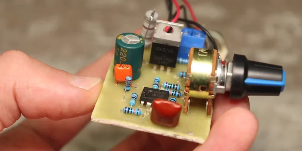
Completed PCB of DIY Soldering Station