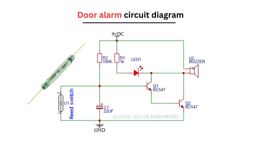
In this article I’m sharing Door alarm circuit using Reed switch. When the door opens, the magnetic field is removed from the door. The switch opens/closes and the buzzer sounds an alarm. This simple DIY project diagrams and connection sharing with you.
Door Alarm Circuit Diagram
This given circuit diagram is easy to build using few number of electronic components. The total cost of the circuit will be under 5$. If you are a electronics hobbyist or looking a simple circuit to build this will be the better choice.
Components Required
| Sl. No | Component Name | Specification / Value | Quantity |
|---|---|---|---|
| 1 | Reed Switch (U1) | Normally Open (NO) | 1 |
| 2 | Resistor (R1) | 1 kΩ | 1 |
| 3 | Resistor (R2) | 100 kΩ | 1 |
| 4 | Capacitor (C1) | 22 µF (Electrolytic) | 1 |
| 5 | Transistor (Q1) | BC547 (NPN) | 1 |
| 6 | Transistor (Q2) | BC547 (NPN) | 1 |
| 7 | LED (LED1) | Standard (Red/Any color) | 1 |
| 8 | Buzzer (U2) | 9V DC Buzzer | 1 |
| 9 | Power Supply | 9V Battery | 1 |
| 10 | Connecting Wires | — | As needed |
| 11 | Magnet | Small permanent magnet | 1 |
Quick Sense | 120 dB Loud Door and Window Open Alarm Sensor | Wireless Safety Alarm for Kids, Dementia Patients | Home, Pool, Cabinet, Business Security | Easy Installation | Pack of 1
- ✅ 120 dB Loud Alarm for Instant Alert
- ✅ Wireless & Battery Powered Security
- ✅ Quick and Easy Installation
- ✅ Complete Package for Home Safety
As an Amazon Associate, I earn from qualifying purchases.
🔥 Check Price on AmazonConnection and Working
The circuit is powering using a 9V DC supply or 9V battery. Where the positive terminal is connected to the top rail and the negative terminal of battery to the ground connection. A reed switch is connected between the base of BC547 transistor and ground.
This reed switch is acting as a magnetic sensor for the door. When the door is closed, the reed switch remains closed, pulling the base of transistor Q1 of BC547 to the ground and keep the circuit in inactive state.
The Resistor R2 of 100K is provides a pull up bias to the base of transistor Q1, while capacitor of 22µF is connected across the base and ground to provide a small delay and noise filtering
When the door is in open condition, the reed switch is opens and it allowing the base of transistor Q1 to receive bias voltage through the resistor R2. This activates the transistor Q2 of BC547. These will forming a switching stage and that drives the buzzer.
At the same time, current flows through resistor R1 of 1K and the LED1. Which will cause the LED to glow as a visual indication. The buzzer is connected to the collector side of the transistor. When the transistor Q2 conducts, it completes the circuit to ground and produces sound in buzzer, which will alerting that the door has been opened.