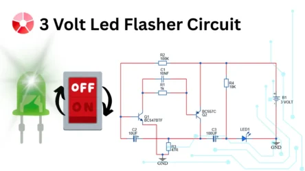
Build an easiest led flasher circuit is not a difficult task, This BC547 LED flasher circuit is a simple and low cost electronic circuit used to blink an LED at regular intervals. This circuit is a very good project for beginners, hobbyists and students who want to understand the basic transistor switching and timing concepts. It uses two general purpose transistors of BC547 and BC557, a resistor and a capacitor to generate oscillations that turn the LED ON and OFF automatically.
Circuit Overview
This LED flasher circuit operates from a 6V DC power supply. You can use batteries or power adapter to power it. The circuit is mainly build with a BC547 (NPN) and BC557 (PNP) transistor pairs. The charging and discharging action of the capacitor creates a time delay, which causes the LED to flash continuously without any external controlling.
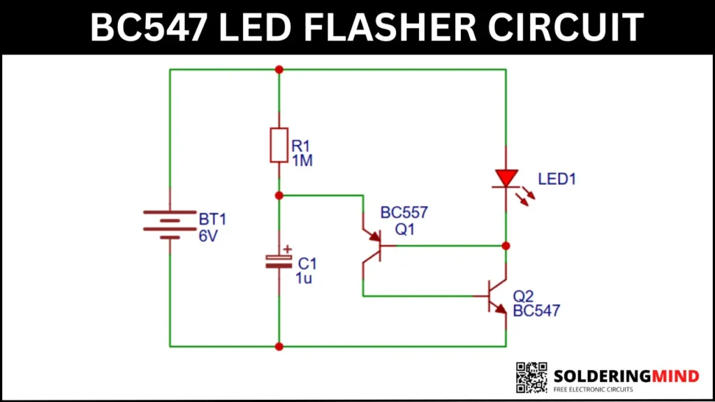
BC547 LED Flasher Circuit Diagram
Universal Safety Signal Aircraft Blinking Strobe 7 Colors Led Light Multipurpose Waterproof for Motorbike (Pack Of 4), Plastic, Battery Powered, Multi-Coloured
As an Amazon Associate, I earn from qualifying purchases.
Components Required
| Component | Value / Type | Quantity |
|---|---|---|
| Q1 | BC557 | 1 |
| Q2 | BC547 | 1 |
| R1 | 1MΩ | 1 |
| C1 | 1µF | 1 |
| LED1 | Any color LED | 1 |
| BT1 | 6V Battery | Battery or adapter |
Working Principle of the Circuit
This LED flasher circuit is working in 6V dc power supply. When you provide a 6V supply to the circuit that time the capacitor C1 is starts to charging through the connected resistor R1 of 1M ohms. The capacitor is fully charged, the voltage is increases which will biases the BC557 transistor.
When the transistor Q1 is turns ON, it will provides a base current to the BC547 transistor and turning it ON. When transistor Q2 is conducts, the current flowing through the connected LED which will causing it to glow.
After some time the capacitor discharges. This time the charge from the capacitor is reducing also the base voltage of transistor Q1 gets stopped. This switches OFF both transistors and turning the LED OFF. The cycle of charging and discharging is then repeats and which will resulting in continuous LED flashing.
Role of Each Component
- The resistor R1 of 1MΩ is controls the charging rate of the capacitor and determines the flashing speed.
- Capacitor C1 of 1µF value will stores charge and creates time delay
- The transistor BC557 is acts as a control transistor
- BC547 will Drives the LED
- LED is visual indication of oscillation
Conclusion
The BC547 LED flasher circuit is an excellent project for learning transistor based oscillators and basic timing circuits. With the minimal components and straightforward operation, it serves as a foundation for more advanced LED and timing based electronic projects.