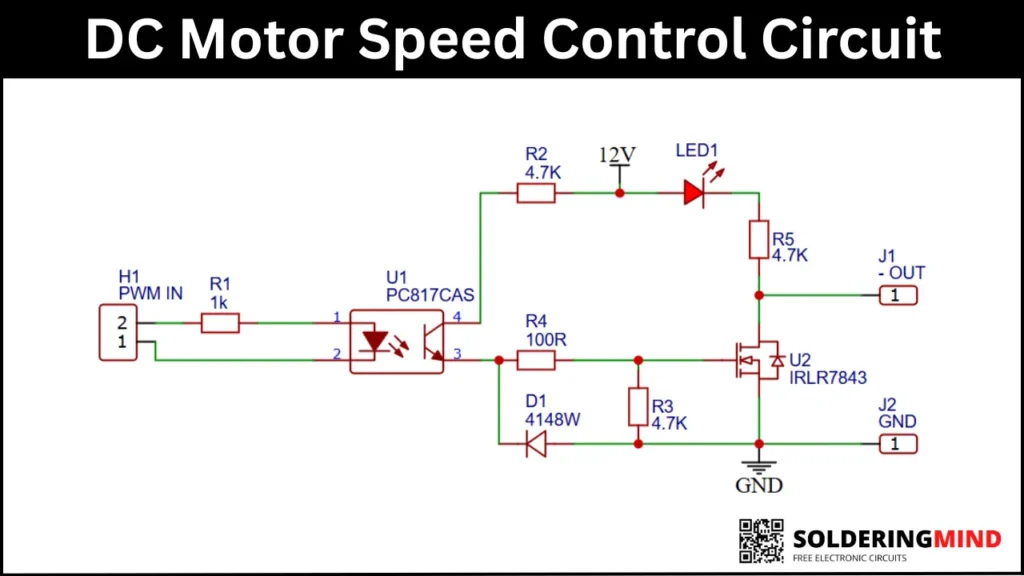
The DC motor speed control circuit is used to precise control over DC motor speed by adjusting the supplied power. Instead of varying voltage directly, this circuit uses a PWM or Pulse Width Modulation. which is more efficient and widely used in modern motor control applications. The circuit uses an optocoupler PC817 for isolation and a logic level MOSFET of IRLR7843 to drive the motor safely and efficiently.
Circuit Overview
This DC motor speed controller works by receiving a PWM signal from a microcontroller like Arduino or a PWM generator. The PWM signal is optically isolated, conditioned and then used to switch a power MOSFET that controls the motor connected at the output.
Features of the circuit
- PWM based speed control.
- Electrical isolation between control and power sections.
- High efficiency MOSFET switching.
- LED indication for power status.
DC Motor Speed Control Circuit diagram
REES52 LR7843 Mosfet control Module Replacement Relay
As an Amazon Associate, I earn from qualifying purchases.
Components Required
| Reference | Component Name | Value / Part Number |
|---|---|---|
| U1 | Optocoupler | PC817CAS |
| U2 | N-Channel MOSFET | IRLR7843 |
| R1 | Resistor | 1kΩ |
| R2 | Resistor | 4.7kΩ |
| R3 | Resistor | 4.7kΩ |
| R4 | Resistor | 100Ω |
| R5 | Resistor | 4.7kΩ |
| D1 | Switching Diode | 1N4148W |
| LED1 | LED | Red LED |
| H1 | Connector | 2-Pin Header |
| J1 | Connector | 1-Pin Terminal |
| J2 | Connector | 1-Pin Terminal |
| — | DC Motor | As required |
| — | Power Supply | 12V DC |
Working Principle
The working principle of this circuit is easy to understands, A PWM signal is applied to the input connector. This connector is connected to the PC817 optocoupler IC pin number 1 and 2.
When a PWM signal is detected the internal LED turns ON and the optocoupler isolates and transfers the PWM signal to the power side.
The MOSFET gets the power to turn ON from the optocoupler IC, which will turn the switches ON and OFF (MOSFET ON or OFF) according to the PWM duty cycle.
🟠 Higher duty cycle > higher average motor voltage > higher speed.
🟠 Lower duty cycle > reduced motor speed.
Additional Tips while designing the circuit
- Use a proper heatsink for the MOSFET if driving high current motors.
- Ensure correct PWM frequency (typically 1 kHz – 20 kHz).
- Add a flyback diode across the motor if not already included.
- Use thick PCB traces for motor current paths.
Conclusion
This DC motor speed controller is easy to build and very efficient in working. In market this board is comes like a module, DC motor speed control module. The main advantage and efficient controlling is happening dew to the PWM signal based mosfet control. This project is simple and ideal for both hobbyist and professional electronics projects. If this project is helpful to you please share opinions in comments, thanks.