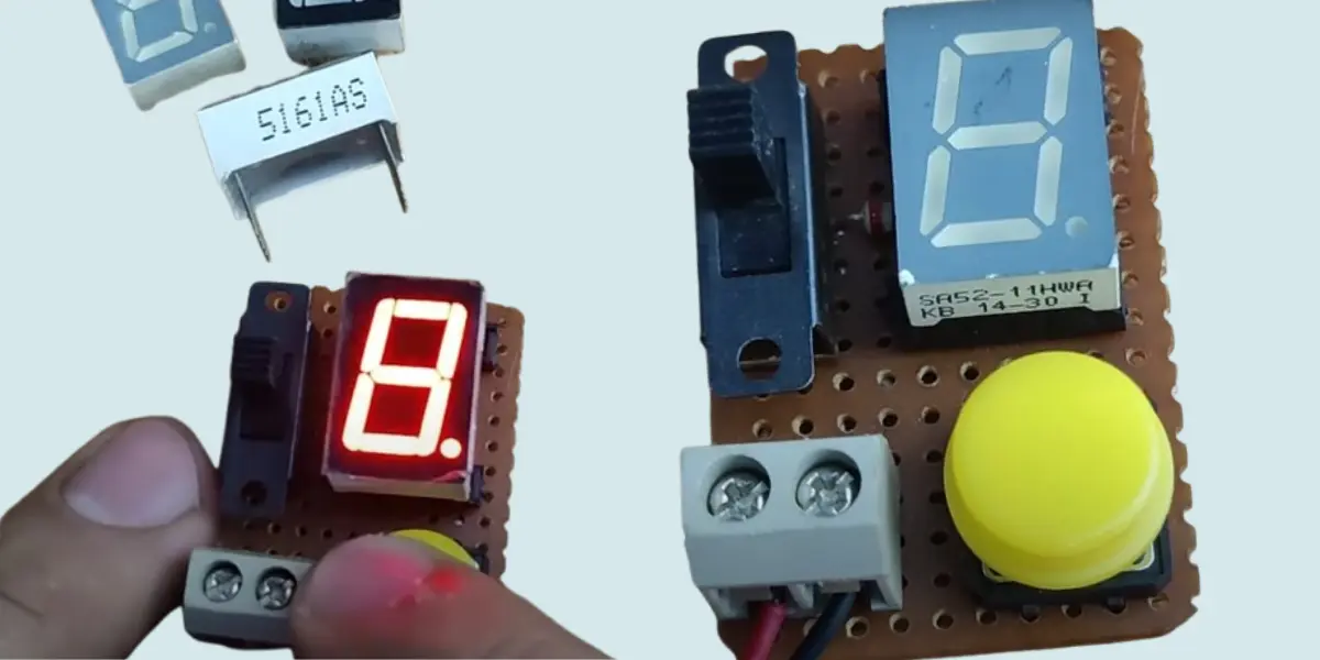
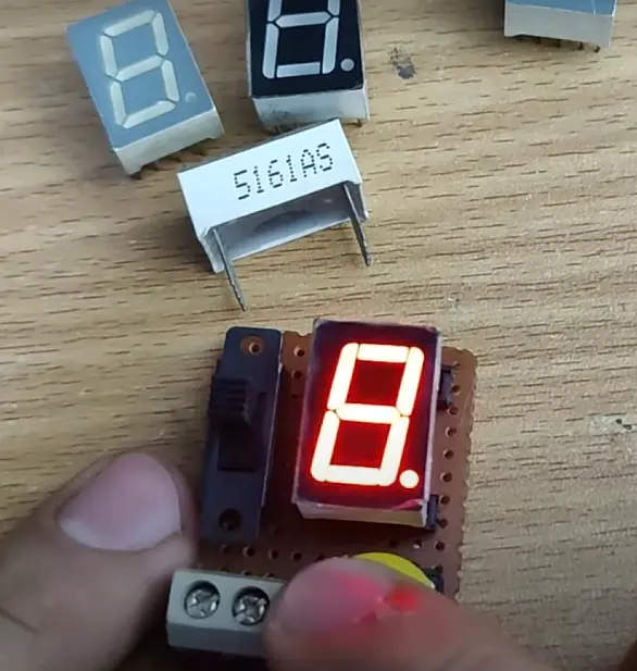
The seven segment display tester circuit is very useful electronic project to checking the display is working properly or not. We can test anode or cathode display before connecting it to an electronic project. The circuit helps to identify the faulty segments, wiring issues, or damaged displays without needing a microcontroller or complex circuits.
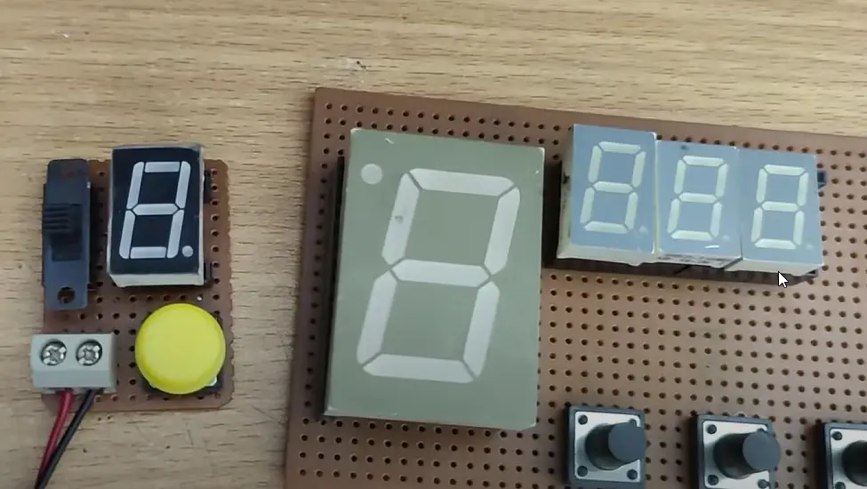
The tester circuit simply connecting the display to the tester and presses a button. When pressing the button we can see all segments light up correctly. This saves time and effort especially when troubleshooting. We can also identify the faulty display as quick as possible.
Seven Segment Display Pinout

Seven Segment Display
The seven segment display is a small electronic screen used in most of the display circuits which shows numbers. It has seven LED segments arranged in the shape of an “8.” The LED turns different segments on or off then the display can show the numbers from 0 to 9. The display also has a decimal point (DP) for showing decimal numbers.
There are two types of seven segment displays are available which are Common Anode displays and Common Cathode displays. The common anode display all the positive terminals are connected together and the segments light up when their negative terminals are connected to ground. In a common cathode display all the negative terminals are connected together, and the segments light up when their positive terminals are connected to positive voltage.
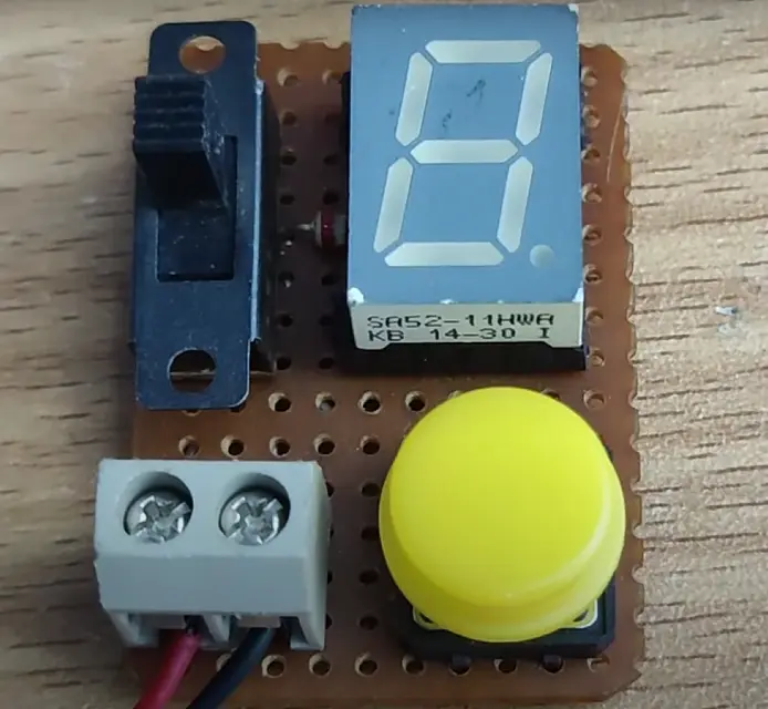
Seven Segment Display Tester Circuit
Components Required
| Component | Specification/Details |
|---|---|
| Seven-Segment Display | Common Anode or Common Cathode |
| Power Supply | 9V DC Battery or Adapter |
| Resistor | 220Ω (Ohms) |
| Push Button | Normally Open (NO) Switch |
| Connector Terminal | 2-Pin Screw Terminal for 9V Input |
| Wires | Various Colors for Connections |
| Two way switch | switch to change polarity |
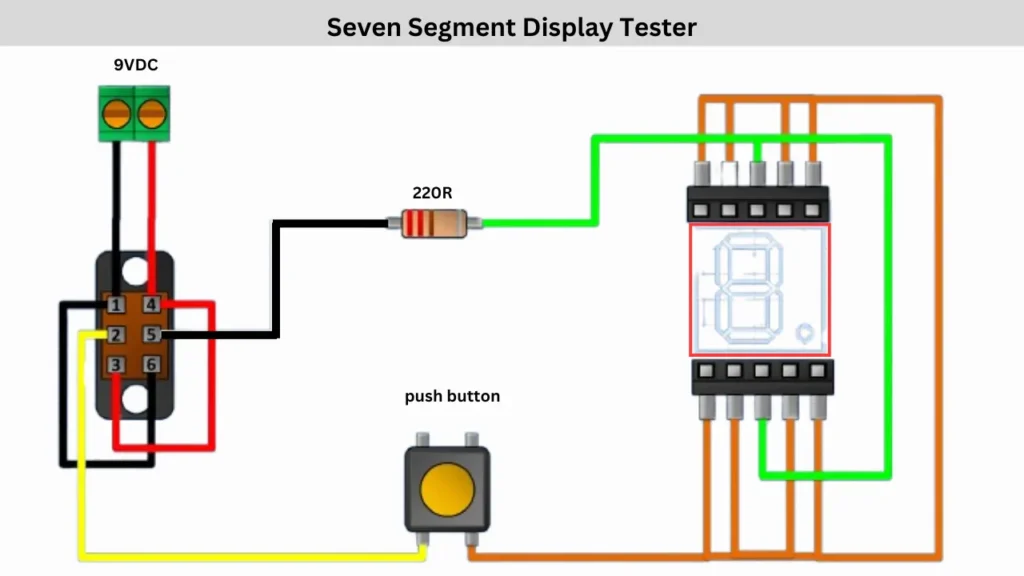
Connection and Working
The connection is starting from the 9V DC power supply. Connect the power to the two way switch pins and then the switch center pin are connecting to the 220Ω resistor in series with the power line and it will limit the current and protect the display. Another connects to the push button.
A push button is used to control the segments by on or off when pressing. One side of the button is connected to the switch and the other side is connected to the individual segment pins of the display through wires. When the button is pressed current is flows through the selected segment, lighting it up. Each segment can be tested by connecting it to the circuit one at a time. This circuit is helps to verify whether all LED segments are working correctly before using this display in a project.