A 20 LED VU meter circuit visually represents the intensity of an audio signal fed into the signal input pin of the circuit. This circuit is also known as a sound level indicator where the LED lights glow up sequentially based on the amplitude of the input signal.
20 LED VU Meter Circuit

The circuit is typically used in audio systems, mixing consoles, and amplifiers to provide a real time display of sound levels. The core components of the circuit is BC547, resistors, diodes (1N4148), and LEDs, which work together to process and display the signal.
Components Required
| Component | Specification | Quantity |
|---|---|---|
| LED | 3mm or 5mm (Any Color) | 20 |
| Transistor | BC547 (NPN) | 20 |
| Resistor | 1kΩ | 20 |
| Resistor | 10kΩ | 20 |
| Diode | 1N4148 | 20 |
| Power Supply | 5V or 9V DC | 1 |
| PCB Board | – | 1 |
| Signal Input | Audio Source | 1 |
Uses of 20 LED VU Meter
This simple VU meter circuit is used in audio engineering, music production, and sound systems to monitor audio signals and confirm the proper sound levels. It helps prevent distortion by providing a visual cue of signal strength.
Based on this level you can adjust volume levels accordingly. The VU meters are found in home theater systems, car audio setups, and professional recording studios to maintain audio quality and balance across stereo channel.
Connections and Working of the 20 LED VU Meter
The 20 LED VU meter circuit consists of BC547 transistors, resistors, diodes and LEDs. It will visually represent an audio signal’s intensity by glowing in a pattern. The circuit is powered by a DC supply of 5V or 9V.
The positive supply is connects to the anodes of all LEDs and the negative is connects to the common ground. The audio signal input is fed through a 10kΩ resistor and a 1N4148 diode to the base of the first BC547 transistor.
Based on the signal strength it passes it to the next stages of BC547 and diode connection group. Each transistor acts as a switch it will control the LED illumination based on the signal strength.
The collector of each transistor is connected to the cathode of a corresponding LED Legs and the Transistor emitter pin is connected to ground. A 1kΩ and 10kΩ resistor in series with each transistor’s base helps regulate the current flow.
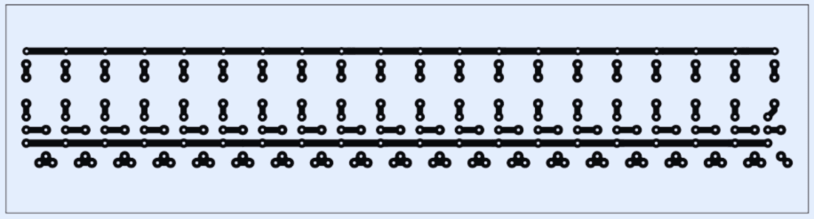
PCB Layout