The PAM8403 amplifier board is in your hand or planning to buy one? Before buying the amplifier board, studying the circuit board and its specifications is important, so in this article I’m sharing the PAM8403 connection details and diagrams for easy installation to your audio system.
What is the PAM8403 Audio Amplifier?
The PAM8403 is a mini class D audio amplifier board. This board provides 3 W stereo output (dual-channel, left and right, each at 3 W) at 4-ohm speaker impedance. The board’s operating voltage is about 2.5 V to 5.5V. This amplifier board is common in any electronics shop because of its popularity in audio DIY projects.
PAM8403 Amplifier Board Pinout
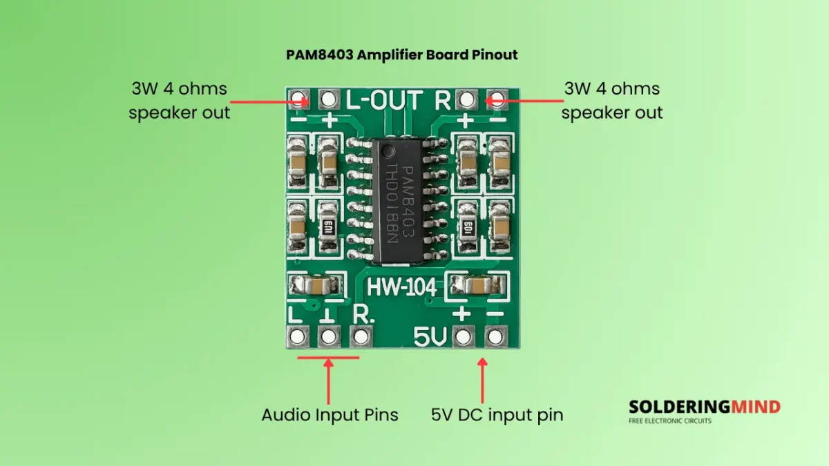
| Parameter | Value |
|---|---|
| Amplifier IC | PAM8403 |
| Supply Voltage | 2.5V–5.5V DC (5V recommended) |
| Output Power | 3W + 3W @ 4Ω (5V Supply) |
| Speaker Impedance | 4Ω–8Ω |
| Channels | Stereo (2-Channel) |
| Amplifier Type | Class-D |
PAM8403 Connection Diagram
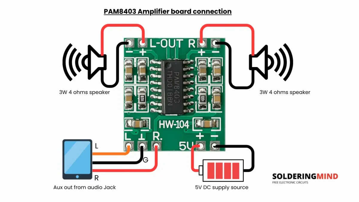
| Terminal | Connection | Description |
|---|---|---|
| 5V + | +5V DC Power | Connect to the positive terminal of a regulated 5V power supply. |
| 5V − | GND | Connect to the negative (ground) terminal of the 5V power supply. |
| L | Left Audio Input | Connect the left channel audio signal from the audio source. |
| Center GND (between L & R) | Audio Ground | Common ground for the left and right audio input signals. |
| R | Right Audio Input | Connect the right channel audio signal from the audio source. |
| L-OUT + | Left Speaker + | Positive terminal of the left speaker. |
| L-OUT − | Left Speaker − | Negative terminal of the left speaker. Do not connect to GND. |
| R-OUT + | Right Speaker + | Positive terminal of the right speaker. |
| R-OUT − | Right Speaker − | Negative terminal of the right speaker. Do not connect to GND. |
How to Connect the Power Supply
The PAM8403 amplifier board requires a 5V DC power supply to turn ON. To get better performance, a regulated 5V DC power supply is needed. You can use Lithium ion batter based supply, a USB adapter, a power bank, or a dedicated DC power supply with a 5V output. If the voltage exceeds 5.5V DC will burn the amplifier board or components.
In the audio amplifier board, the markings are visible as 5V and +ve and -ve labels. Connect the same polarity to the 5V power supply connection. A reverse connection will kill your amplifier IC, so be careful with the connection. I recommend using a 3A diode if you are repeatedly connecting and disconnecting the power supply. This will protect from an accidental polarity-reversed connection. The diode blocks current in reverse bias.
How to Connect the Audio Input
This amplifier module comes with a stereo output, so you need to provide a stereo audio signal to it. The marking of “L” for left, “G” for ground, and “R” for right channel to connect from the audio source. If you are using a 3.5 mm stereo jack, wiring should be straightforward. This is the standard connection for most of the mobiles and aux cables. If you are attaching a Bluetooth audio receiver board, you can directly connect using small wires to the same markings of left, right and ground pin.
How to Connect the Speakers
The speaker connection marking is labelled as L-/+ out and R-/+ out. The L labelled section is left channel and connected to left speaker and R labelled is right channel connects to the right channel speaker. Important note is “not to connect the speaker negative to the ground” connection. Here, negative means the speaker negative pin, not the ground or power supply negative. You can use 3 watt 4 ohms or 8 ohms speaker with this board. After checking the connections properly, turn on the board and check the sound by increasing the volume gradually.
PAM8403 Wiring with Common Audio Sources
- Smartphone (3.5 mm Headphone Jack).
- Laptop or PC Connect the headphone.
- Bluetooth Audio Receiver Module
- IN MP3 Player module wire the stereo output to the L, R, and GND input terminals.
- FM Radio Module.
Power Supply Recommendations
You can use a regulated 5V DC power supply for powering the amplifier board. The power supply current needs to be 1 A to 2 A; it is enough to power the module with good sound quality. You can use a 5V 2A UBS adapter for building a DIY audio system. If you want to power the circuit from 12V or 24V, you can use a DC to DC buck converter to get a stable 5V Dc supply. Avoid an unregulated power supply or an adapter connection to prevent audio distortion and noise.
Common Wiring Mistakes to Avoid
- Provide regulated 5V DC supply with 1-2A current.
- Speaker negative connection is not the ground connection so don’t mix with them.
- Listening music in maximum volume will reduces the life of the board.
- Connect with 3W 4 or 8 ohms speaker.