The PAM8403 is a 3 Watt Class D audio amplifier IC. Used for making tiny audio amplifiers which works on 5V DC power supply. The circuit provide stereo 3 watt at 4 ohms speakers. so this board is very suitable for car audio amplifiers. In this article i’m sharing the circuit diagram and connection details of this PAM8403 amplifier circuit.
PAM8403 Amplifier Circuit Diagram
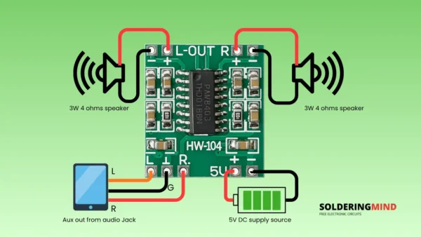
Connection Explained
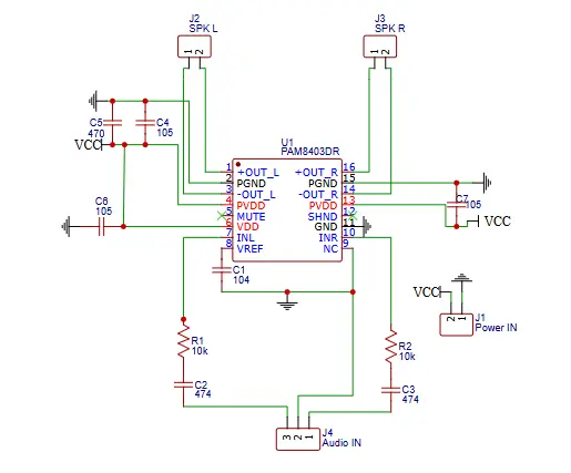
The circuit is based on the PAM8403 3W class-D stereo amplifier IC. This PAM8403 (U1) which is the receives audio signals via the INL (pin 6) and INR pin 11. INL and INR is representing the left and right audio inputs. These inputs are filtered with RC networks (R1/C2 and R2/C3) to reduce high-frequency noise. Capacitor C1 (100nF) is connected to the VREF pin (pin 7). This will helps in stabilizing the internal biasing of the amplifier. The MUTE and SHDN (shutdown) pins are directly connected to VDD (pin 8) and it enabling normal operation of the amplifier.
The audio output is taken from pins of OUTL+ (pin 1), OUTL− (pin 3) for the left channel and OUTR+ (pin 14), OUTR− (pin 12) for the right channel. These differential outputs are connected directly to the left and right speakers. Bypass capacitors C4, C5 (for left) and C6, C7 (for right) are used to filter out DC offsets and noise from the power lines. Additional decoupling is provided by capacitor C8, stabilizing the power supply input.
The power supply is connected via connector J1, where VCC powers both PVDD (pins 4 and 13) and VDD (pin 8), while the GND connections are tied together and connected to the circuit’s common ground. The audio input comes through connector J4, where left and right signals are separated and filtered before being fed into the amplifier. This configuration enables a compact and efficient stereo amplifier suitable for low-power applications like portable speakers or USB-powered audio devices.
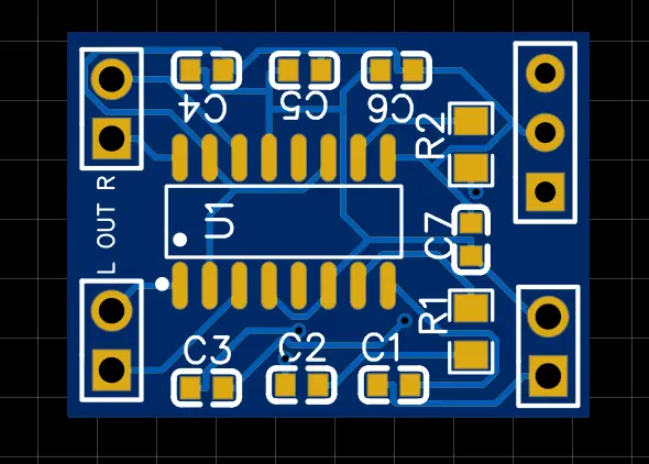
PCB Layout and 3D Model