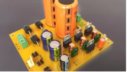
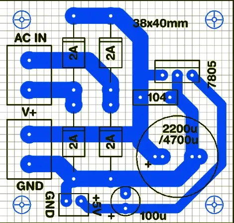
The bridge rectifier with a 7805 voltage regulator-based circuit is easy to build on a dotted PCB. This circuit converts the AC voltage from the transformer into a stable DC voltage using a full-wave bridge rectifier and also converts the high-voltage DC into a 5 V auxiliary power supply. This article also shares the circuit diagram, working, and PCB layout so you can build it yourself.
Use of This Bridge Rectifier Circuit with 5V Regulator
- Converts AC voltage from a transformer into DC voltage.
- Provides a stable and regulated 5V DC power supply.
- Powers 5V electronic circuits, microcontrollers, sensors, and other small devices.
Bridge Rectifier with 7805 5V Regulator circuit Diagram
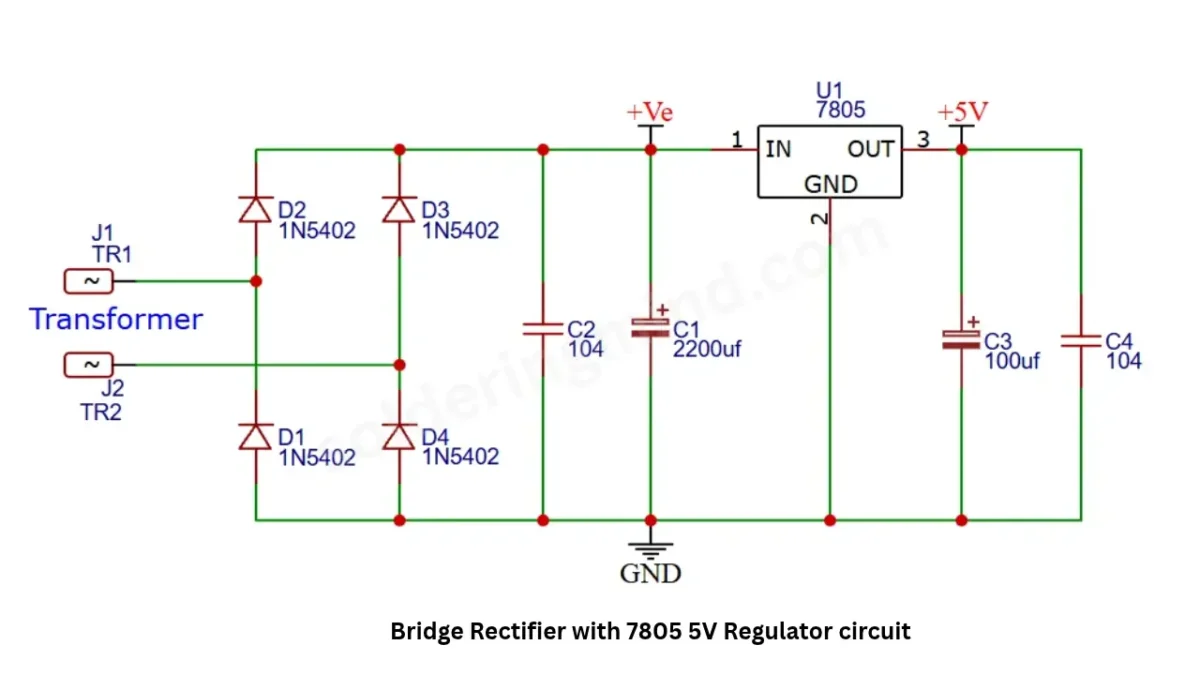
This circuit is designed with few electronic components including four 2-3A diode and large electrolytic capacitor and 5V regulator IC of LM7805. The circuit gives two separate power supply outputs, one is the direct filtered supply of transformer and the another one is regulated 5 volt supply from the 7805 regulator IC.
PCB Layout
Also Check: 24v to 5V power supply circuit
Components Required
| Sl. No. | Component Name | Specification | Quantity |
|---|---|---|---|
| 1 | Voltage Regulator IC | 7805 (5V) | 1 |
| 2 | Rectifier Diode | 1N5402 | 4 |
| 3 | Electrolytic Capacitor (C1) | 2200µF | 1 |
| 4 | Ceramic Capacitor (C2) | 100nF (104) | 1 |
| 5 | Electrolytic Capacitor (C3) | 100µF | 1 |
| 6 | Ceramic Capacitor (C4) | 100nF (104) | 1 |
| 7 | Step-Down Transformer | Suitable AC output voltage | 1 |
| 8 | Connecting Wires | As required | As needed |
Connections and Circuit Working Principle
You need to connect the secondary wire of the step-down transformer to the AC input terminal of the circuit. The four 1N5402 bridge rectifiers rectify the AC voltage to pulsating DC voltage. The connected 2200uf capacitor is used for DC filtering and smoothing the DC output voltage. The 100nf capacitor is connected in the circuit to reduce unwanted noise production in the circuit.
Transformer and Filter Capacitor Voltage
In this circuit i didint mentioned the transformer voltage and 2200uf electrolytic capacitor. This circuit will work up to 35 volts. This is because the regulator IC’s maximum input voltage is up to 35 V. So you can use a transformer of up to 24 V to get around 26V-28V DC output, which is safest for the regulator IC.
Download PCB Layout
Conclusion
This AC-to-DC bridge rectifier-based circuit with an additional 5V auxiliary supply is a useful circuit for audio amplifiers. If you want a beautiful and highly efficient power supply board, you can defenitly try this. You can change the circuit for your requirements by replacing the 7805 with a 7812 for 12V stable output.