In automobile and inverter circuits a 12 or 24 batteries are using for powering the electrical circuits. Do you want to convert the 24V dc voltage to 5V dc voltage? Yes you can convert high voltage DC voltage to low voltage DC for mini fans or sensors or microcontrollers. So in this article I’m sharing the 24V to 5V DC converter circuit using MP1584 SMD IC.
MP1584 Buck Converter

The MP1584 IC is a high efficiency step down DC-DC buck converter widely used in electronic projects and power supply circuits. IC can able to delivering up to 3A output current with excellent load and line regulation. This compact switching regulator operates at high frequency and integrates an internal power MOSFET for optimal performance.
This IC based circuit is Ideal for Arduino, Raspberry Pi, robotics, and custom DIY electronics circuits. The MP1584 IC based module offers adjustable output voltage, thermal shutdown, short-circuit protection, and overcurrent protection features. So this IC based circuits is reliable choice for compact and energy efficient power conversion. Whether you’re building battery powered systems or embedded hardware, the MP1584 is a trusted solution for efficient voltage regulation.
MP1584 Pinout
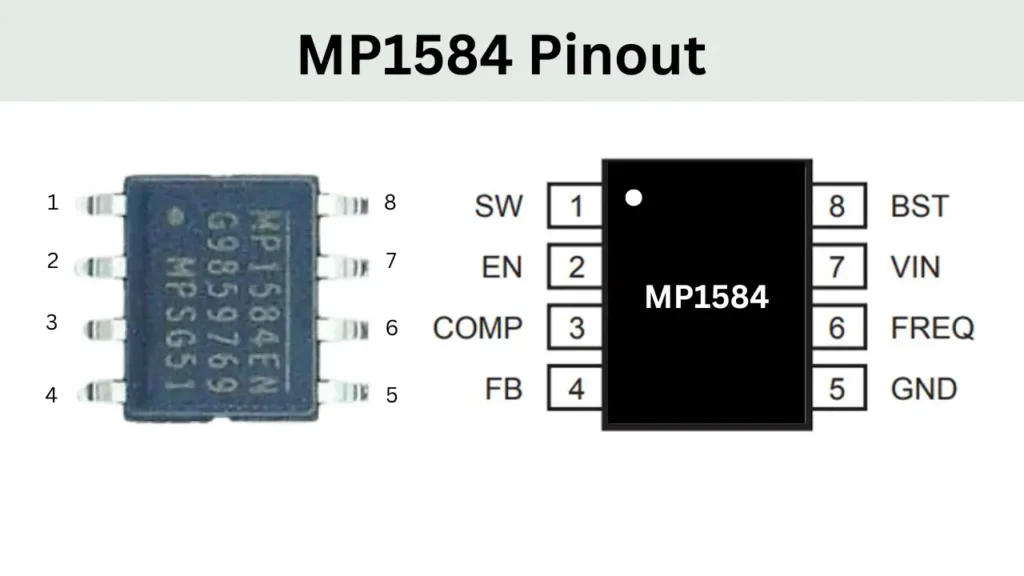
| Pin No. | Name | Description |
|---|---|---|
| 1 | SW | Switch Node (Output) |
| 2 | EN | Enable Input |
| 3 | COMP | Compensation Pin |
| 4 | FB | Feedback Input |
| 5 | GND | Ground |
| 6 | FREQ | Frequency Set |
| 7 | VIN | Input Voltage Supply |
| 8 | BST | Bootstrap Pin |
Components Required
| Component | Value |
|---|---|
| U1 | MP1584EN |
| R1 | 210kΩ |
| R2 | 40kΩ |
| R3 | 100kΩ |
| R4 | 24.9kΩ |
| R5 | 100kΩ |
| R6 | 100kΩ |
| R7 | 40kΩ |
| C1 | 10µF |
| C2 | 22µF |
| C3 | 150pF |
| C4 | 100nF |
| L1 | 4.7µH |
| D1 | SS34A |
| LED1 | LED-0805_G |
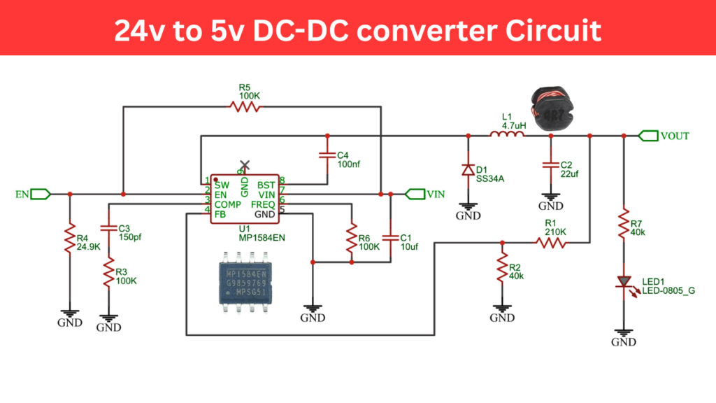
24V to 5V DC DC Converter Circuit Diagram
Working of DC DC converter Circuit
The 24V to 5V DC DC converter circuit is based on the MP1584EN step down converter IC that efficiently reduces a higher DC voltage to a stable lower output voltage. In this circuit a 24V DC input is fed into the VIN pin of the IC, also a capacitor C1 (10µF) is used to filter the input noise. The switching frequency is determined by resistor R6 value of 100kΩ it is connected to the FREQ pin.
Inside the MP1584EN, a high speed switching process is used to chop the input voltage and this switched signal is sent out through the SW pin. The external components L1 (4.7µH inductor) and D1 (SS34A Schottky diode) form part of the output stage, where the inductor smooths out the pulsed voltage, and the diode allows current to continue flowing when the switch is off.
The output is further stabilized using capacitor C2 (22µF). This will providing a steady 5V DC output. A feedback mechanism using resistors R1 (210kΩ) and R2 (40kΩ) samples the output voltage and feeds a divided voltage back to the FB pin of the IC. This allows the MP1584EN to regulate the output by adjusting the duty cycle of its internal switch, keeping the output at a constant 5V even when the load or input voltage changes. For loop compensation and stability, R3 (100kΩ) and C3 (150pF) are connected to the COMP pin, tuning the internal error amplifier.
The EN pin is used to enable or disable the converter. It is pulled high with R5 (100kΩ) to keep the IC active, and can be pulled low via R4 (24.9kΩ) to shut down the circuit. A bootstrap capacitor C4 (100nF) between the SW and BST pins enables the high side MOSFET to switch properly. Additionally, an LED indicator (LED1) is connected at the output through resistor R7 (40kΩ), lighting up when 5V is present. This entire setup ensures an efficient and reliable conversion from 24V to 5V, suitable for powering low-voltage electronics from higher-voltage sources.