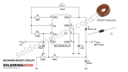
This DC to DC converter is working based on a DC to DC converter IC of MC3406. This circuit and PCB is designed to step up 12V Dc to 15V DC 2A supply. This project is essential for the circuit need higher voltage to work. This project circuit diagrams and PCB Layout is sharing with you at free of cost. You can download and build this at home.
Overview of Boost Converter Operation
- The boost converter is a device or electronic circuit which will increases the DC voltage from a lower input voltage level to a higher voltage level (e.g., 12V to 15V).
- It uses main components like inductor, transistor or mosfet for switching, diode and capacitors.
- The circuit is works by storing energy in the inductor when the switch is ON and releasing it to the output when the switch is OFF (MOSFET turn on and OFF).
- The output voltage is higher than the input voltage what we are given due to the inductor’s energy discharge.
- Operates in two main phases
- Switch ON condition, the Inductor get charged.
- In Switch OFF condition, the Inductor will discharges through the diode to the output.
- The MC34063 IC controlling the switching, timing and regulation automatically.
- Output voltage is regulated by adjusting the duty cycle (ON/OFF time)
MC34063 IC Features and Functionality
- This IC supports Step-Up (Boost), Step-Down (Buck), and Inverting converter configurations.
- Input Voltage Range from 3V to 40V and it is suitable for various applications.
- Adjustable Output Voltage set using external resistors.
- Integrated Switching Components of Internal NPN switch witch is rated up to 1.5A peak current.
- Internal oscillator (typically 100 kHz) for controlling switching frequency.
- Current limiting feature to protect against overload.
- Thermal shutdown for IC safety.
- The IC can achieve up to 85% efficiency with proper design.
- Minimizes the external components so it is ideal for space constrained circuits setup.
12V to 15V Boost Converter Circuit Diagram
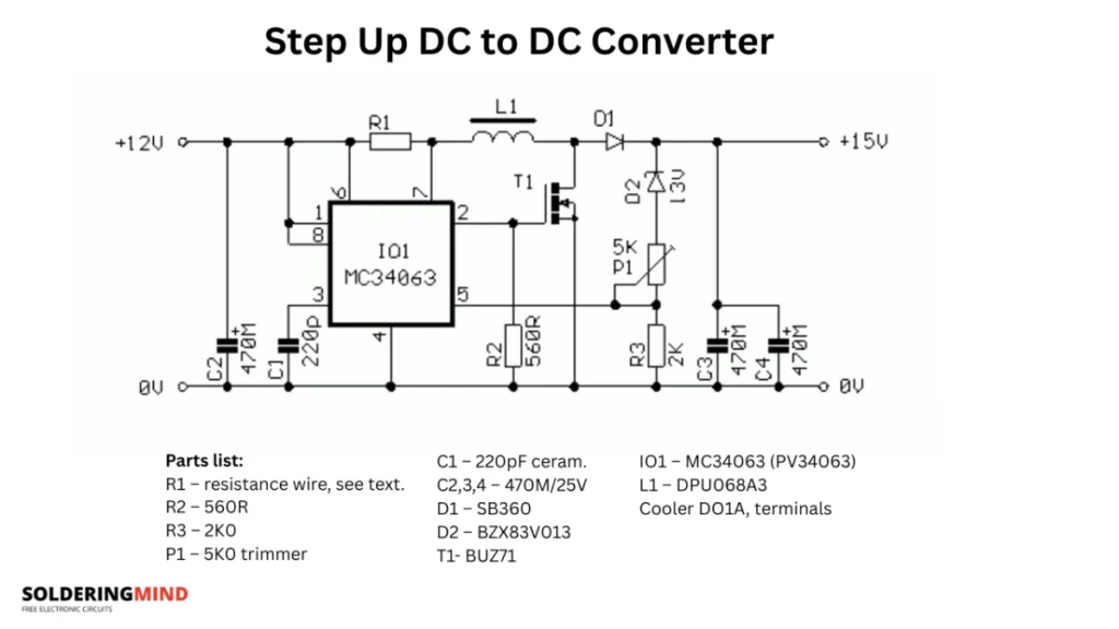
Design Calculations for Voltage Boost
The Resistors R2 and Potentiometer P1 sets the output voltage of 15V DC. Adjusting the Pot P1 will changes the output voltage. So set the value based on your requirements
Pin number 3 of the IC sets the Timing for Turn ON and off the Mosfets, Typical value of the capacitor is 470 pF to 1.5 nF For ~100 kHz, use Ct ≈ 220Pf is enough.
Choose an inductor that supports peak current > 1.5A, So i recommended to use the coil inductance is about 68 µH to 3A toroid coil.