Buck converters are the electronic circuits which are used to converting the high voltage DC voltage in to lower voltage and in stable output voltage it will maintain. So in this article I’m sharing the simple SMD based buck converter circuit. You can build this circuit at home for powering DC fans, other electronic sensors and modules.
SJ2B (LMR14206) Regulator IC
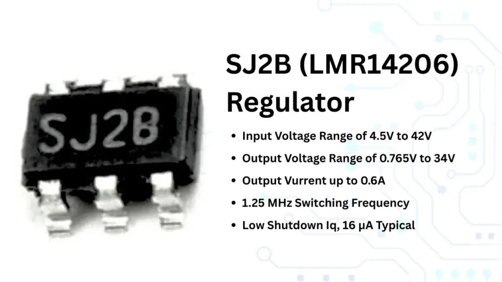
The SJ2B Regulator or LMR1406 is a sad based DC to dc buck converter IC. This IC is comes in SOT-23 packaging. The input voltage of this IC is between 4.5V to 42V DC supply. Due to this wide range of input voltage , this IC is a perfect choice for high voltage electronics circuits. The out put voltage of this IC is 0.765V to 34V DC.
This buck converter is working based on PWM control of internal IC circuit. Maximum output current will be 600mA, it means 0.6A of current. The maximum efficiency of this IC is 85%. This IC is working in a fixed pwm frequency of 1.25Mhz. The soft start of this IC is determined by the RC circuit connected with the Shutdown pin of the IC.
Features
- Input voltage is 4.5 to 45V DC.
- Output voltage can be controlled within the voltage range of 0.765 to 34V DC.
- Output current is about 600mA.
- PWM switching frequency is 1.25Mhz.
- Soft start option.
- 6 pin SOT Packaging
SJ2B or LMR1406 Pinout
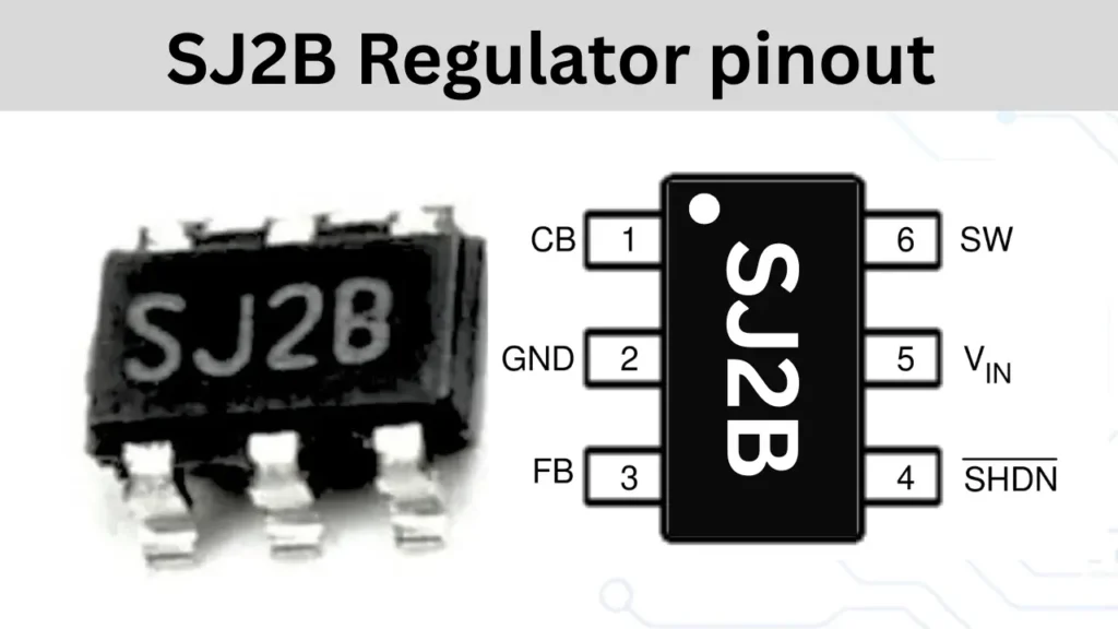
| Pin Number | Pin Name | Function |
|---|---|---|
| 1 | CB | Compensation or Bootstrap Capacitor |
| 2 | GND | Ground |
| 3 | FB | Feedback |
| 4 | SHDN | Shutdown (active low) |
| 5 | VIN | Input Voltage |
| 6 | SW | Switch Node (Output to inductor) |
Circuit diagrams
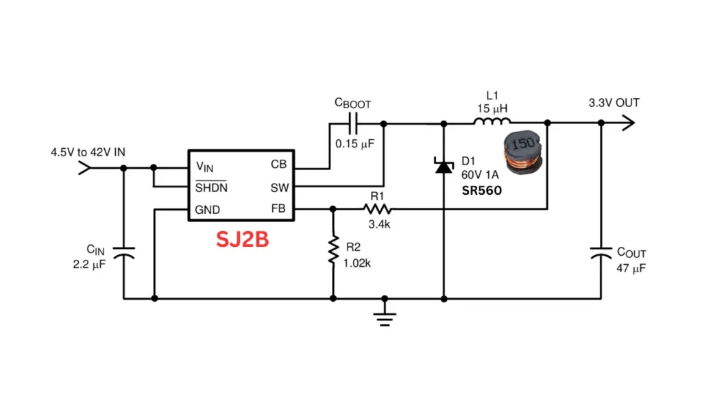
The SJ2B Regulator IC based circuits are given below. Based on the output voltage the different circuit configuration is given here. The fig 1 represents the 3.3v buck converter circuit. In this different circuit configuration only the feedback connected resistor values will be change.
In Fig 2 the output voltage will be 5V Dc the input voltage will be 7 volt to 42 volt. The R1 and R2 is the voltage divider and it is connected to the feedback pin. Which will controlling the output voltage and Here the R1 value is 5.6K and R2 is 1.02K resistors.
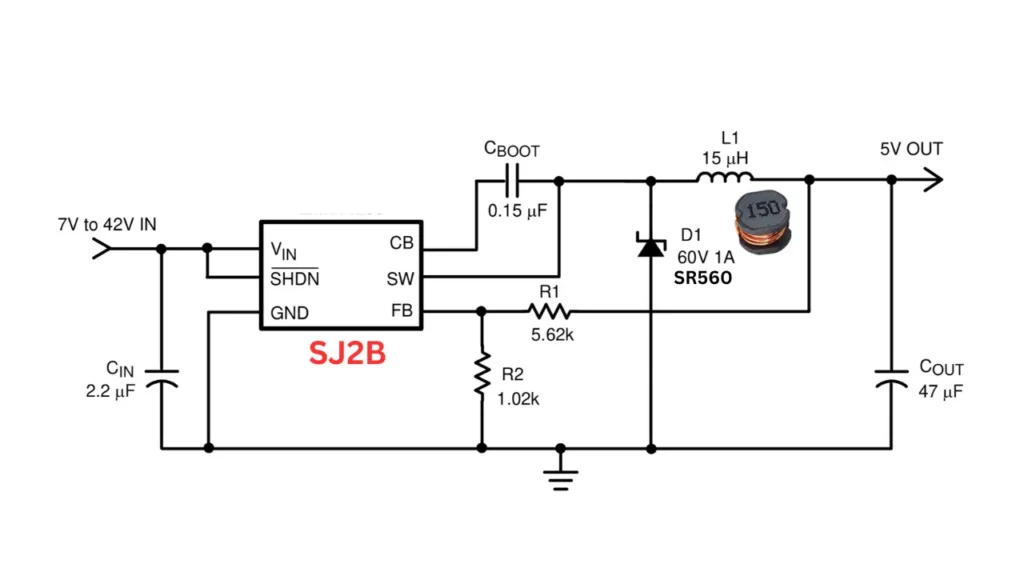
The output voltage can be adjusted by changing the values of R1 and R2. The common power supply voltage of 3.3v, 5v,12v and 15v circuit voltage dividers values are given below.
| Output voltage | Value of R1 | Value of R2 |
| 3.3V | 3.4K | 1.04K |
| 5V | 5.62K | 1.02K |
| 12V | 14.7K | 1K |
| 15V | 28K | 1.5K |