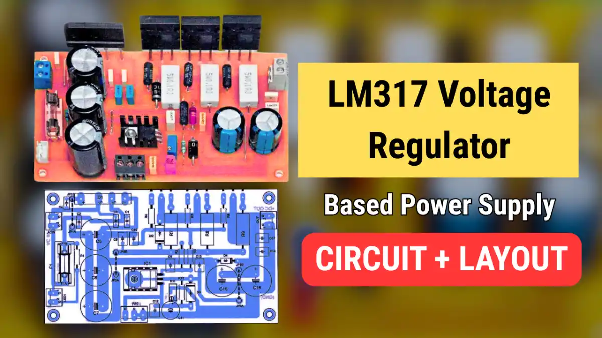
This LM317 voltage regulator based circuit is designed for get the stabilized power supply for sensitive electronics circuit with low noise and minimal interference. The circuit used LM317 IC and three power transistors to handle current above 5A. So in this article you will get the schematics and PCB Layout for Free.
Why This Circuit is Important
- Using LM317 it gives a stabilized output voltage.
- Adjustable from 1.25V up to 24V DC output.
- The circuit can handle current above 5A.
- Simple design and easy to build.
- Power is distributed to the three power transistors, so minimal heat dissipation.
LM317 Voltage Regulator Circuit Diagram
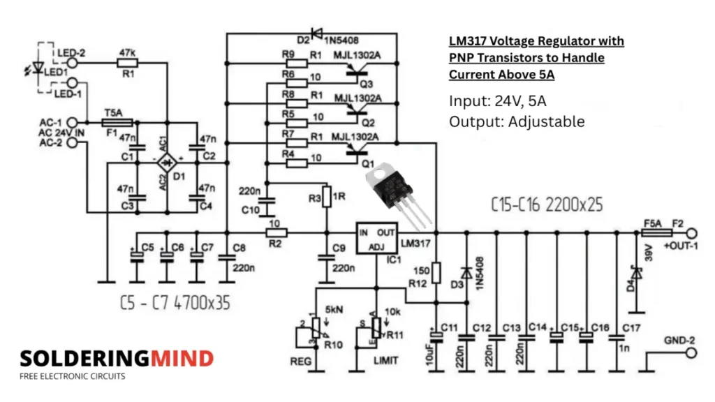
Connections and Working
This voltage regulator circuit using the main regulating IC of LM317 for stabilizing the output voltage. A 24V Transformer is used to provide the input voltage source. This circuit configuration can able to handle current of 5 ampere or more.
In this configuration a 220v to 24V 5A step down transformer is used. The transformer providing the maximum power output of around 150Watt. The 24V output is connected with a bridge rectifier to rectify the AC voltage to DC.
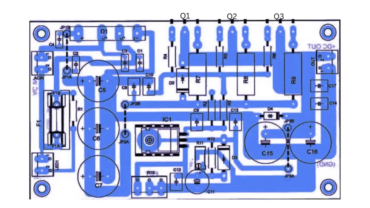
Three 4700uf/50v capacitor is using as a capacitor bank to DC filtering from the rectifier. The PNP power transistors of Q1 to Q3 is connected in parallel. Which will increases the overall current handling of the circuit. More transistors means more current it can able to handle.
This circuit added a protection features like input fuse with LED fuse failure indication and output fuse to protect the over current or short circuit protection. The Recommended transistors are in TO-264 package types such as MJL1302, MJL21193, MJL4302.
- The LM317’s minimum output voltage is ~1.25V (its internal reference).
- A multi-turn potentiometer (e.g., 3590S or PM-534) is recommended for fine voltage adjustment.
- Potentiometers should be shunted with parallel capacitors to avoid induced unwanted voltage due to inductance.
- A trimmer resistor (~5 kΩ) can be used in series with the potentiometer to adjust the minimum voltage.
- The upper voltage limit is set using trimmer resistor R11.
- It’s important to ensure capacitor voltages (C5 and C7) are not exceeded.
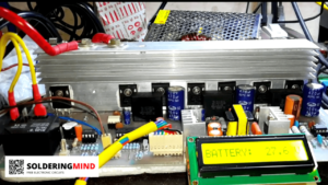
- Transistors and the rectifier are mounted on the PCB edge for easier heatsink installation.
- Voltage and current measuring devices can be added to the output for monitoring.
