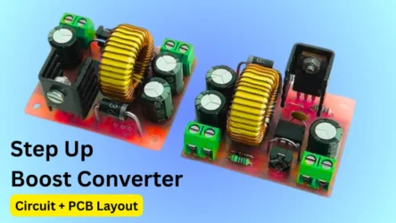
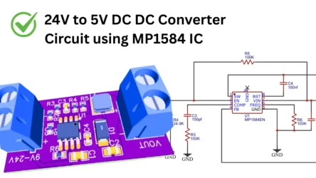
The MT3608 boost converter is a small DC-DC step up module used in many electronic circuits such as DIY projects and sensor circuits. It will convert the 2.4V into 24V DC at the output. This module is perfect for powering the 5V to 12V utilizing devices which needs a stable voltage. You can use a single lithium ion battery to power the board. if you are planning to build a portable audio amplifier or DIY project using a low voltage battery, this boost converter board will helps you. In this article I’m sharing the circuit diagram to build a boost converter using the MT3608, working principle, features and applications.
What is the MT3608 Boost Converter?
It is a DC to DC voltage boost converter board using MT3608 IC. the board can boost the 2V input voltage to maximum of 28V DC, this can be adjustable using the potentiometer. This board is offering 93% of high efficiency in switching operation. If you are build a battery powered device this board is very useful for stable power supply. You can use this board with 3.7V lithium ion batteries to do DIY projects also. This lightweight module offers thermal shutdown and current limiting protection features.
MT3608 Module
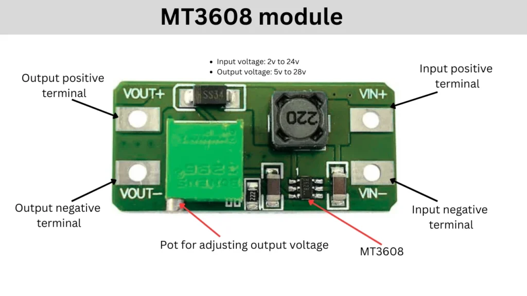
Specifications and Features
- Input Voltage Range: 2V to 24V DC
- Output Voltage Range: Adjustable up to 28V DC
- Maximum Output Current: Up to 2A (recommended is 1A for stable performance)
- Switching Frequency: 1.2 MHz
- Efficiency: Up to 93%
- Chip Type: MT3608 (SOT23-6 package)
- Load Regulation: +/- 0.5%
- Voltage Regulation: +/- 0.5%
MT3608 Pinout

Pinout Configuration
| Pin Number | Pin Name | Function |
|---|---|---|
| 1 | SW | Switch pin (drain of internal MOSFET) |
| 2 | GND | Ground |
| 3 | FB | Feedback voltage input |
| 4 | EN | Enable pin (active high) |
| 5 | IN | Input voltage |
| 6 | NC | Not Connected |
MT3608 Circuit Diagram
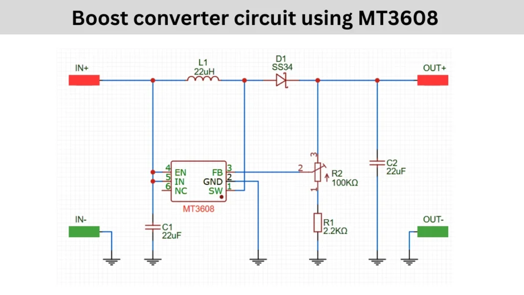
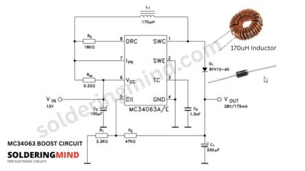
In this circuit The IN+ and IN- is labeled as the DC input voltage and it is around 2v to 24v DC. Pin 1 of MT3608 is connected to the L1 and D1. Pin2 is connected with the ground connection. Pin3 is connected to the voltage divider R1 and R2, this voltage divider is used as a Feedback purpose.
Pin4 is enable option which is connected to the positive input voltage pin, so it activated when the input voltage is detected. when the circuit is turned on the current will flow through the inductor and the inductor is storing the energy, when the circuit turns of the stored energy is released. The on and off is controlled by the internal circuit of the IC. The switching frequency is around 1.2Mhz.
Output Voltage Formula
Vout = Vref(1+R2/R1)
- Reference Voltage (V_REF) of MT3608 FB pin = 0.6V
- R1 = 2.2 kΩ
- R2 = 100 kΩ (potentiometer, adjustable)
At maximum R2 value 100K ohms the output voltage from the module is calculated as,
Vout = 0.6(1+100000/2200)
Vout = 0.6(1+45.45) ≈27.87V
Applications
- Powering 5V devices from a single Li-ion cell (3.7V).
- DIY electronics.
- Battery-powered devices needing voltage step-up.