The A1013 Transistor is also marked as 2SA1013, which is a PNP transistor with high voltage and medium power. This transistor is common in old CRT monitor boards for the vertical deflection circuit and the audio amplifier driver stage. In this article, I’m sharing the A1013 Pinout, equivalent transistor for replacement, and its specification information for quick analysis.
What Is the A1013 Transistor?
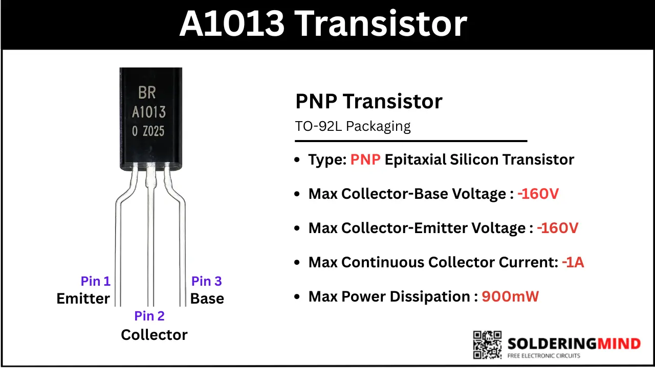
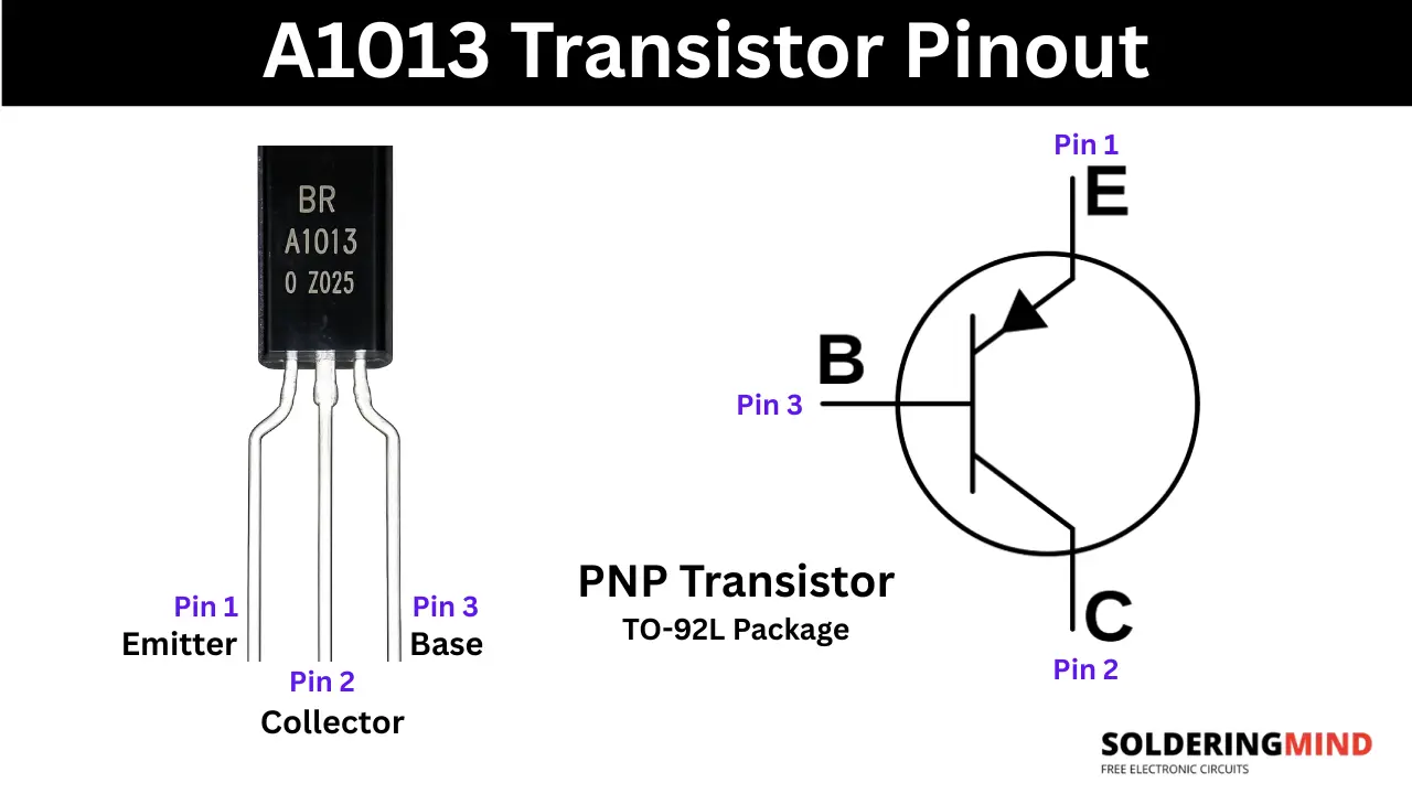
A1013 is a PNP transistor, comes in TO-92L plastics package. The Collector emitter voltage of -160V and collector current of 1A.
A1013 Transistor Pinout Diagram
To check the pinout of the transistor, you need to hold the transistor number facing you and pins are pointing downward. Then count the pins from left to right as 1, 2 and 3. The first pin is emitter, second pin is collector and third is Base. Which is represented in the diagram below.
A1013 Pin Configuration and Functions
The transistor comes in TO-92L Packaging and the pin configuration and pin functions rea given in the table below.
| Pin No. | Pin Name | Function |
|---|---|---|
| 1 | Emitter (E) | Supplies charge carriers (holes) into the transistor and is usually connected to the positive supply voltage. |
| 2 | Collector (C) | Collects the current flowing through the transistor and connects to the load. |
| 3 | Base (B) | Controls the transistor’s switching and amplification action with a small input current. |
A1013 Transistor Specifications
- Package Type: TO-92L (slightly larger than standard TO-92 packaging).
- Collector-Emitter Voltage is 160 V.
- Collector Current is1 A (Continuous).
- Collector Dissipation is 900 mW.
- Transition Frequency is 50 MHz.
How the A1013 Transistor Works
The A1013 is a BJT transistor; this transistor controls a large current using a smaller input current in the base pin. In normal conditions, the emitter pin is connected to a positive voltage. When the base gets enough voltage (slightly lower than the emitter voltage), the transistor will turn ON and allow current to flow from the emitter to the collector pin. This function is useful for signal amplification and electronic switching circuits.
A1013 Transistor Equivalent and Replacement
You can directly replace using 2SA1275, KTA1275, 2SB1212 transistors and compatable replacements are 2SA1020, 2SB647 and TIP42C
Complementary Transistor
The complementary transistor for 2SA1013 is 2SC2383 NPN transistor. You can use this pair of transistors in push pull configuration.
Common Applications of the A1013 Transistor
- This transistors are used in color Tv vertical deflection and class B audio amplifier stage.
- Used in switching application, DC to DC converters and high voltage power supply circuits.
- Relay and LED driver circuit as switch ON or OFF.
Advantages of Using the A1013 Transistor
- The transistor has high voltage handlining capacity of -160V.
- High current can handle up to 1A.
- Low collector emitter saturation voltage, so the power loss and heat generation is less.
Testing the A1013 Transistor with a Multimeter
Testing the B-E and B-C Junctions
Turn the multimeter knobs to diode mode and test Collector-base and emitter base readings. Place the red probe on Base and black probe on collector first and emitter second. On each testing you need to get a voltage range between 0.5 to 0.7V which means the transistor is good.
Checking Short and Leak
| Red Probe On | Black Probe on | Expected Reading | Status |
|---|---|---|---|
| Emitter (Pin 1) | Base (Pin 3) | OL (Over Limit / 1) | ✅ Good |
| Collector (Pin 2) | Base (Pin 3) | OL (Over Limit / 1) | ✅ Good |
| Emitter (Pin 1) | Collector (Pin 2) | OL (Over Limit / 1) | ✅ Good |