A buck converter is an electronic circuit that steps down from high voltage to low voltage. A DC-to-DC buck converter is essential in different applications, such as Audio amplifiers, LED circuits, and other power supply circuits. Those Buck converters efficiently convert high-voltage DC to low-voltage DC.
Introduction to the Buck Converter
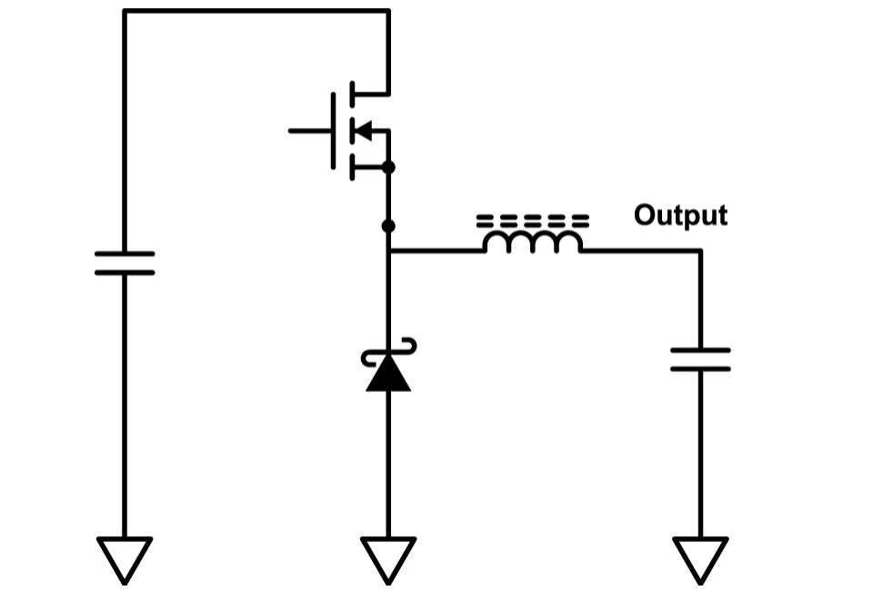
A Buck converter is a very simple circuit. Figure 1 is a model circuit of a buck converter. The circuit contains a Mosfet, PWM controlling IC, Schottky Diode, and a toroid core with copper winding coil.
The DC transferring function is an equation that relates to the input voltage, output voltage, and also the duty cycle. V out = Vin *D where the V out is the voltage in the output section, Vin is the voltage input, and D is the duty cycle. ( or the percentage of the time that the Mosfet turns on in the circuit ).
The low pass filter ( the toroidal winding coil ) smoothes the MOSFET switching action and produces a nice and smooth DC voltage in the output.
Basic Buck Converter Diagram
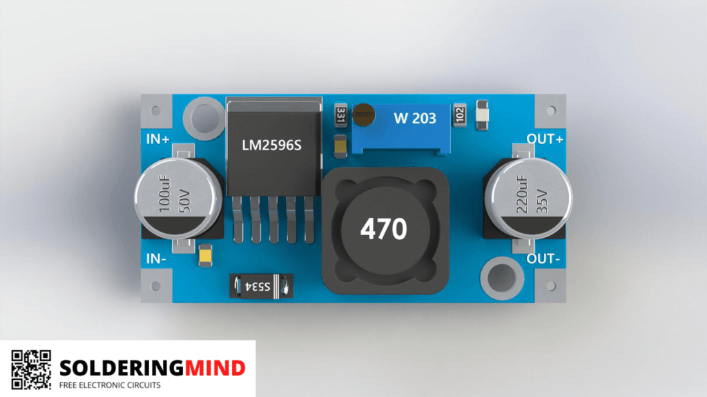
Buck Converter Module in the Market
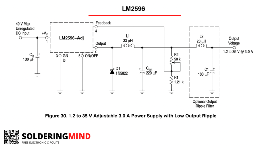
LM2596 Buck Converter Circuit
Components Required
| Part Number | quantity |
| LM2596 | 1 |
| 100uf capacitor | 1 |
| 1N5822 diode | 1 |
| 33uH coil | 1 |
| 220uf/63v capacitor | 1 |
| 50K preset pot | 1 |
| 1.21k ( 1.2k) resistor | 1 |
| power supply | 1 |
| wires | – |
| connectors | – |
LM2596/LM 2596 DC to DC Buck Converter/Regulator, Dc-Dc Step Down Adjustable Voltage Power Supply
- The buck converter consists of thickened circuit boards, high-Q inductance with output LED indicator, and superior solid-state capacitors that can effectively filter out high frequency noise. Suitable for various electronic projects.
As an Amazon Associate, I earn from qualifying purchases.
🔥 Check Price on Amazon