This automatic bike headlight dimmer circuit switches between bright and dim light modes depending on the surrounding light conditions. It is a Smart Auto-Dimming Bike Headlight, works with a single BD139 transistor and 12V relay. You can place the LDR sensor based on your requirements. This article shares the circuit and its working principle to build yourself.
Why I am Using This Circuit In My Motorcycle
- It automatically switches between bright and dim headlight modes based on the surrounding light conditions, without requiring manual operation.
- Better Riding Convenience by reduces the need to operate the headlight switch frequently, allowing me to concentrate more on the road.
- The 10K potentiometer allows me to adjust the LDR sensitivity according to the surrounding light conditions.
Automatic Bike Headlight Dimmer Circuit Diagram
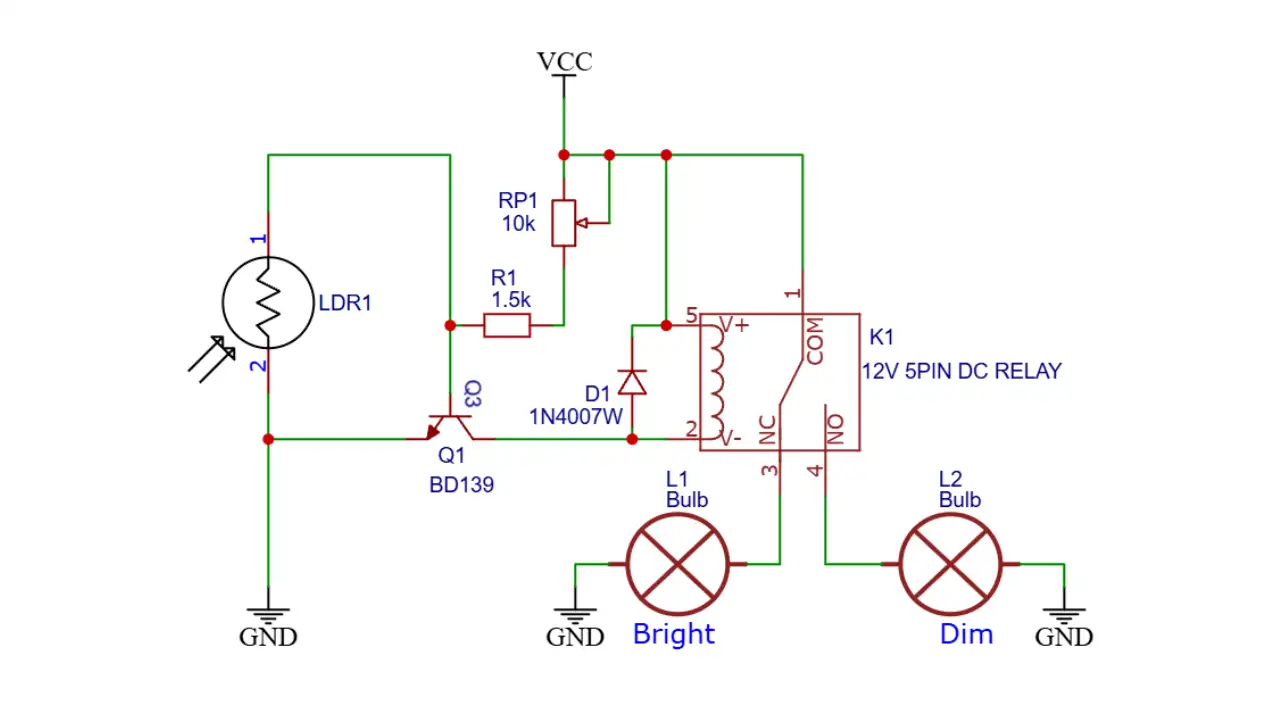
Note: Use a 12V DC relay and a suitable 12V power supply. The bulbs should be rated according to the bike’s electrical system and relay contact capacity.
Components Required
| Sl. No. | Component Name | Specification | Quantity |
|---|---|---|---|
| 1 | LDR | Light Dependent Resistor | 1 |
| 2 | Transistor Q1 | BD139 NPN Transistor | 1 |
| 3 | Potentiometer RP1 | 10KΩ | 1 |
| 4 | Resistor R1 | 1.5KΩ | 1 |
| 5 | Diode D1 | 1N4007W | 1 |
| 6 | DC Relay K1 | 12V, 5-Pin SPDT Relay | 1 |
| 7 | Bulb L1 | Headlight Bulb (Bright) | 1 |
| 8 | Bulb L2 | Headlight Bulb (Dim) | 1 |
| 9 | Power Supply | 12V DC | 1 |
Circuit Connection
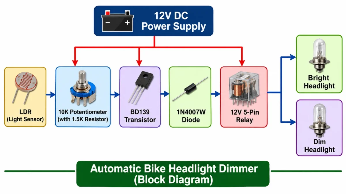
The LDR one pin is connected to ground, and the other one goes to the BD139 transistor base pin. The BD139 collector pin is connected to the relay coil pin. The transistor acts like a switch for the relay coil.
1.5K resistor and a 10 K potentiometer control the sensitivity of light and relay activation. By adjusting the 10K pot, you can control the response to changes in surrounding light.
The relay pin is connected to the BD139 collector pin, and the other pin is connected to the positive supply. The Relay coil is controlled by the BD 139 NPN transistor. The 1N4007 diode is connected between the relay supply connection to protect the circuit from reverse voltage generated by the coil.
The relay COM pin is connected to the 12V supply rail, and NC and NO are connected to the Bright and Dim light connections. The other end of the light connection is connected to the ground connection.
Working Principle
This dimmer circuit is based on light sensing property of the LDR. In dark time their is no light falls on the LDR and the resistance is high, when light falls on it resistance reducing and turn off the transistor and which will also turns off the 12V relay and the relay connected light also switches to bright to dim.
Conclusion
This automatic bike headlight dimmer circuit is useful for who are looking to automate the motorcycle bulb when opposite vehicle light comes. The sensitivity of the light response can be controlled by the 10K potentiometer. bye bye for the manual switch operation, try this circuit and enjoy friends.