The 4-way splitter circuit splits an audio signal from one input into four outputs without losing signal strength. This circuit uses TL071 and TL072 op-amp ICs to split the audio signal efficiently. This circuit is commonly using for audio amps needs different audio signals to listen music, movie or podcast. Also this circuits are helpful for studio and live monitoring places.
What is the Use of 4-Way Audio Splitter
- Splits one audio input signal into four separate outputs to connect four amplifiers or audio systems.
- Allows you to adjust the volume of each of the four output channels separately.
- Useful for distributing the same audio signal to multiple monitoring or recording devices.
- Helps to distribute music from a single audio source to four different audio zones or amplifier setups.
4 Way Audio Splitter with Gain Control Circuit Diagram
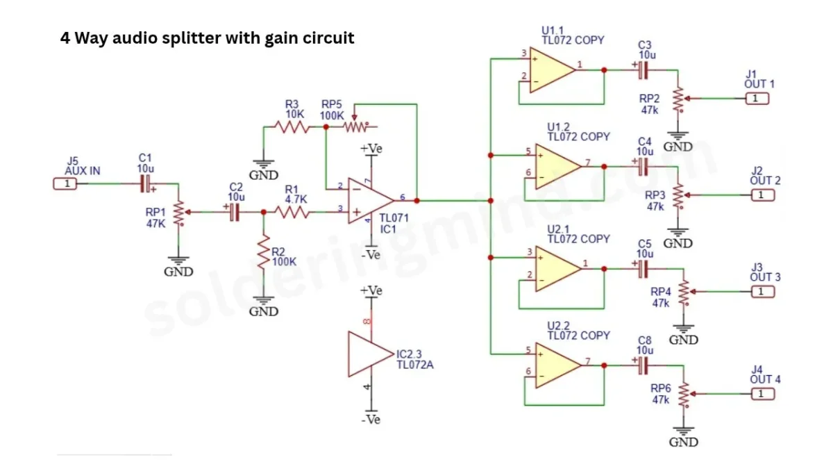
The circuit is very easy to understands, the input section separated using a 10uf electrolytic capacitor and resistors and potentiometer. The TL071 IC is used as audio gainer and provides the boosted audio signal for four output section IC. The TL072 is process the signal and gives output from OUT 1 to OUT4.
Also Check: Mono audio signal to Stereo audio converter Circuit
Components Required
| Sl. No. | Component | Value / Part Number | Quantity |
|---|---|---|---|
| 1 | Operational Amplifier IC | TL071 | 1 |
| 2 | Dual Operational Amplifier IC | TL072 | 2 |
| 3 | Resistor | 4.7KΩ | 1 |
| 4 | Resistor | 10KΩ | 1 |
| 5 | Resistor | 100KΩ | 1 |
| 6 | Potentiometer | 47KΩ | 5 |
| 7 | Potentiometer | 100KΩ | 1 |
| 8 | Electrolytic Capacitor | 10µF | 6 |
| 9 | Audio Input Connector | AUX IN | 1 |
| 10 | Audio Output Connector | OUT 1 | 1 |
| 11 | Audio Output Connector | OUT 2 | 1 |
| 12 | Audio Output Connector | OUT 3 | 1 |
| 13 | Audio Output Connector | OUT 4 | 1 |
| 14 | Dual Power Supply | Positive and Negative Supply (+Ve, -Ve) | 1 |
Supply Voltage Information
The circuit requires a dual power supply with positive (+Ve), negative (-Ve), and ground (GND) connections to operate the TL071 and TL072 operational amplifiers. A symmetrical supply of +12V and -12V DC can be used, provided it is within the operating limits of the ICs. The positive and negative supply voltages are connected to the respective power pins of the op-amps, while the common ground acts as the reference point for the audio signal. A stable, regulated dual power supply is recommended for proper operation and to minimize unwanted noise and distortion in the audio output.
Working Principle
The working principle of this circuit is easy to understand. The circuit starts from the audio input section. The single audio signal is given through the AUX input pin. The signal then passes through the Capacitor C1 of 10uf and, which blocks the unwanted DC voltage from the audio signal. The potentiometer RP1 of 47K which will adjust the input audio volume level.
Then the audio reached the TL071 IC. The TL071 acts like an audio preamplifier, where you can adjust the gain of the audio using a feedback network consisting of resistor R3 and potentiometer RP5. This initial stage amplifies the audio signal to the next required level. This amplified signal is then passed to the four different audio output buffer amplifier stages containing the TL072 IC.
finally the buffered audio signal is passes through the 10uf electrolytic capacitor and a seperate 47kpotentiometer. This individual potentiometer helps to control the individual section’s audio volume level.
PCB Layout Files
Conclusion
The four-way audio splitter circuit with gain control is a useful audio project that allows the single audio input to be divided into four output sections without losing audio quality. This circuit is suitable for connecting multiple audio amplifiers from a single audio source. Overall, the circuit offers the best solution for efficient audio signal distribution.