Lets build a simple High frequency inverter using few electronic components. The circuit can generate up to 500 watt output on 220V AC. The circuit shown in the schematic is a PWM signals based inverter circuit using a TL494 IC. This IC is commonly used for voltage regulation and switching applications like SMPS.
12v DC to 220v AC inverter circuit Schematics
The TL494 operates as a pulse width modulation (PWM) controller which generating switching signals to drive transistors Q4 and Q5. The circuit takes a 12V power input from connector J6. The connector J2 is used to take out the PWM signals generated by the IC.
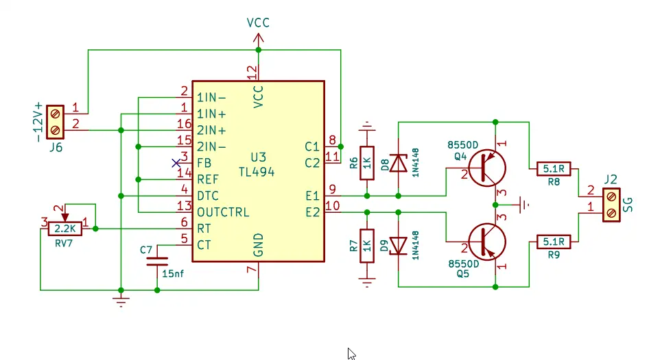
The resistors, capacitors, and diodes around the TL494 set the operating frequency and duty cycle. Resistors R6 and R7 (1K each) help limit current to the base of the transistors, while diodes D8 and D9 (1N4148) protect against back EMF.
Capacitor C7 (15nF) sets the oscillator frequency along with an external resistor. The output transistors Q4 and Q5 act as switches, allowing the controlled current to flow through the load resistors R8 and R9 (5.1 ohms each). This circuit can be used in motor control, power supply regulation, or LED dimming applications where PWM control is needed.
Components Required for Inverter Driver Circuit
| Component Type | Component | Quantity |
|---|---|---|
| Integrated Circuit (IC) | TL494 | 1 |
| Resistors | 2.2KΩ (RV7) | 1 |
| 1KΩ (R6, R7) | 2 | |
| 5.1Ω (R8, R9) | 2 | |
| Capacitors | 15nF (C7) | 1 |
| Diodes | 1N4148 (D8, D9) | 2 |
| Transistors | 8550D (Q4, Q5) | 2 |
| Connectors | J6 | 1 |
| J2 | 1 |
12v DC to 220v AC inverter Power Stage circuit
The circuit uses four IRFZ44N MOSFETs (Q10, Q11, Q12, and Q13) which is N channel Mosfets commonly using in inverter circuits. The Mosfets are connected in push pull arrangement to drive a high-frequency transformer (T1). Each MOSFET is paired with a 33Ω resistor (R39, R40, R49, and R50) to ensure proper gate drive and prevent oscillation. The transformer has a center tapped primary windings. The secondary winding is designed to step up the voltage from 12v to 220V AC.
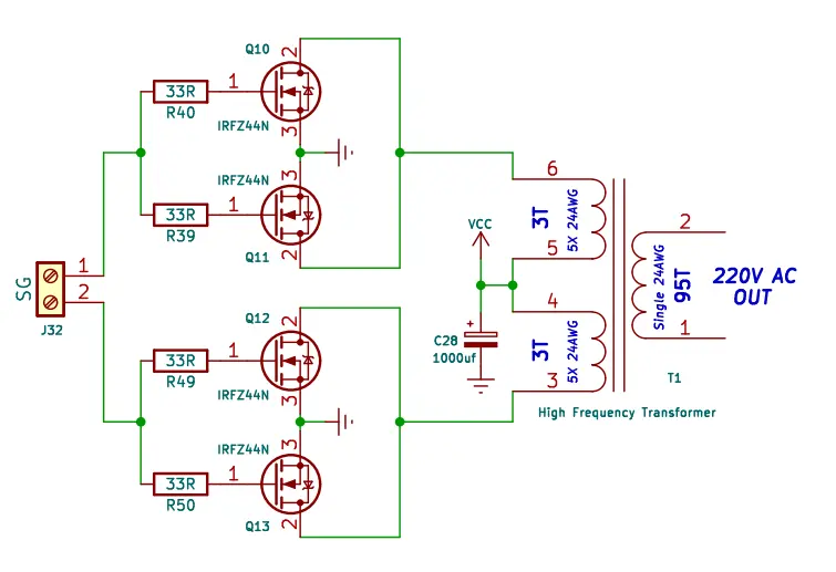
The main component of this power stage circuit is the high frequency transformer (T1), which will convert the 12v DC to High voltage AC current. The primary side consists of three turns of 24AWG wire wound five times on each half. The secondary winding has 95 turns of single 24AWG wire. Proper winding and calculations Stepping up the voltage from the input 12v to 220V AC. The capacitor C28 (1000µF) is placed across the power supply to stabilize the voltage and filter out nois. This will ensuring smooth operation of the power MOSFETs. The circuit receives its input signal from a signal generator (SG) via connector J2, which provides the necessary PWM signal to switch the MOSFETs alternately.
This inverter circuit is suitable for applications requiring high efficiency DC to AC conversion, such as power backup systems or off grid energy solutions. The use of high frequency switching reduces losses and enhances performance. Proper heat dissipation measures, such as heatsinks for the MOSFETs may be necessary to handle thermal stress during the continuous operation.
FAQ
This circuit is designed to convert 12v DC voltage into a 220V AC output using a high frequency transformer and MOSFETs.
The circuit operates by using TL494 and MOSFETs (IRFZ44N) in a push-pull configuration to switch the DC input at high frequencies signals. The modified 12V will be converter to 220V Ac.
The High frequency ferrite core transformer steps up the low voltage DCto high voltage Ac. The high frequency based circuit is design to improves the efficiency and reduces transformer size.


Merhaba
12v DC’den 220v AC’ye çevirici devre şemasının PCB dosyası varmı. Paylaşabilirmisiniz. Teşekkür ederim.
yakında güncelleyeceğim arkadaşım