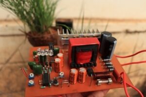
Building a sine wave inverter is a bit complicated, but using an Arduino nano is a very easy and compact design. here I am sharing this project circuit and Arduino nano programming code.
The provided code is for an Arduino Nano, and there are mentions of PWM and an inverter. The setup function configures pins 9, 10, and 2 as outputs, and pin 12 as an input with a pull-up resistor. There’s also some timer configuration using registers like TCCR1A, TCCR1B, ICR1, etc. That part probably sets up a PWM signal with a specific frequency and mode.
Arduino Nano Sine Wave Signal Generator Circuit

The Arduino nano pin 1 is connected to a push button. This button is used as a Reset button, if it is pressed the circuit will restart in soft mode. Pin A0 is the Feedback pin connected to the feedback circuit. Pin D10 and Pin D9 are the PWM out pins to drive the H bridge circuit.
The PWM pin is connected with a 10K resistor and it is fed into the IR2101 IC.
500 Watt Sine Wave H Bridge Inverter Driver Circuit using IR2101 IC

To produce a sine wave signal two PWM signals are injected to the IR2101 IC. PIN 2 and 3 are PWM hi and PWM Low pins, Both are connected to the Pwm A and PWM B of the Arduino Nano connection. PIN 7 of IR2101 is a High output pin and the 5 will be Low output respectively.
The high and Low pins of IR2101 are connected to the H bridge circuit. The H bridge circuit is built with IRFZ44 Medium power MOSFETs. You can use any power N-channel MOSFET for high-current handling.
Feedback Circuit

The feedback is connected from the output transformer and a 1N4007 diode is used to filter the AC voltage and a 10K resistor is used to lower the voltage and current passing through it. A 10 K variable resistor or pot is used to adjust the feedback voltage.
H Bridge Circuit for 500 Watt Inverter

The power Mosfets are connected in an H Bridge configuration. The High and Low signals will be connected from the IR2101 Ic. A 10 K resistor is used in between the Mosfet gate pin and IR2101 signal pins. please make sure that connect a high-quality heat sink to protect the Mosfet from overheating.