The Arduino remote control project will give lots of ideas to develop new electronic projects. A normal Tv or your DVD player can use for this project. Through this circuit, you can able to control the Home appliances by adding an extra relay circuit to this project, so in this article, I would like to share ideas about remote control based Arduino projects.
Circuit Diagram

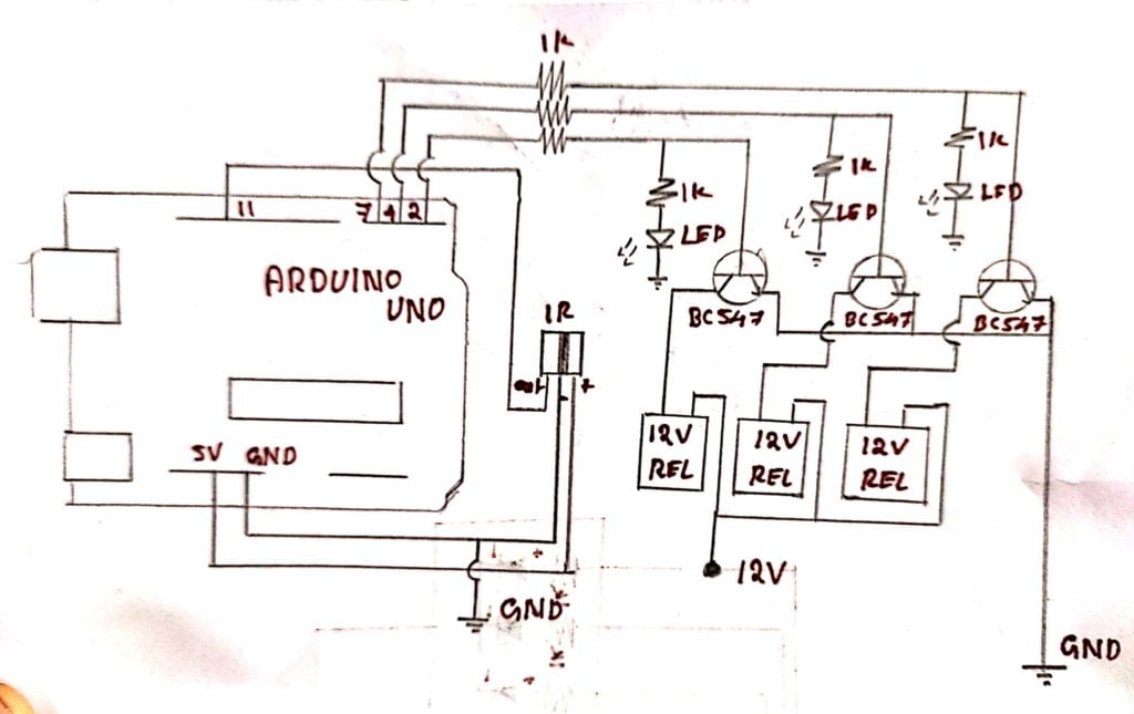
Arduino IR Remote Control Project
The ir remote control working with few components. in this article, a brief explanation is given about the project. For understating of the coding and wiring will be elaborated here. A three LED represents the ON/OFF of each channel when you pressing the corresponding buttons on the remote control.
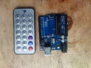
How to setup an ir remote and receiver on an arduino board
Infrared communication is using as an easy wireless technology having more useful applications. The most important and daily using TV/video remote controls.
There are a lot of Arduino remote control projects are using Infrared for communications. With a simple Ir transmitter and receiver, you can build several electronic projects such as Arduino based robotic cars, distance sensor, TV remote jammier, lots more.
The tutorial explains how the infrared works. after that show you how to set up IR remote and Receiver on arduino. to control Led connected to the arduino.
Infrared working
The infrared lights are different from the normal light you will get from the outside. The difference between the normal light and Ir light is in wavelength and frequency. Using this condition we can control particular devices through their receiving device.
IR transmitter and receiver pair working
Infrared communication is working based on the specific wavelength and frequency, for this communication we need an IR transmitter LED and IR receiver. The IR led produces light in the region of the IR spectrum instead of the visible spectrum.
The IR receiver is a photodiode, which will convert the Infrared light to an electrical signal. and it will look like this:
Infrared signal modulation
The IR signals producing by several light sources like sun, normal bulb, or any hot burning thinks, so this will interfere with the transmission of signals. To avoid this interference from other sources the modulation of the signal has to be carried out. The IR remote sends a modulated IR signal to the receiver after the signals to be converted into a binary signal before going to the Arduino.
The modulated signals will be turned on and off IR led at a specific frequency of 38KHz. This frequency is known as a carrier frequency. The receiver only receives this 38kHz frequency and omits the other frequency that comes from the environment.
This binary numbers will be our Key factor for doing this project.
Connecting IR receiver to an arduino board
The IR receiver has three pins.
- Vcc – Positive voltage input.
- Gnd- Ground or negative supply
- Out – The modulated signal output.
- Connect the Output connection of the IR receiver to the Arduino Uno pin 11.
- connect Gnd to the ground supply of the board.
- connect positive supply to the 5v supply from the Arduino Uno board.
After connecting the IR receiver to Arduino we need to get the binary code for specific buttons you pressing in the remote. We need to perform ir sensor Arduino code serial monitor for identifying the specific code for every button in the remote. to do this follow the steps,
Arduino Programming
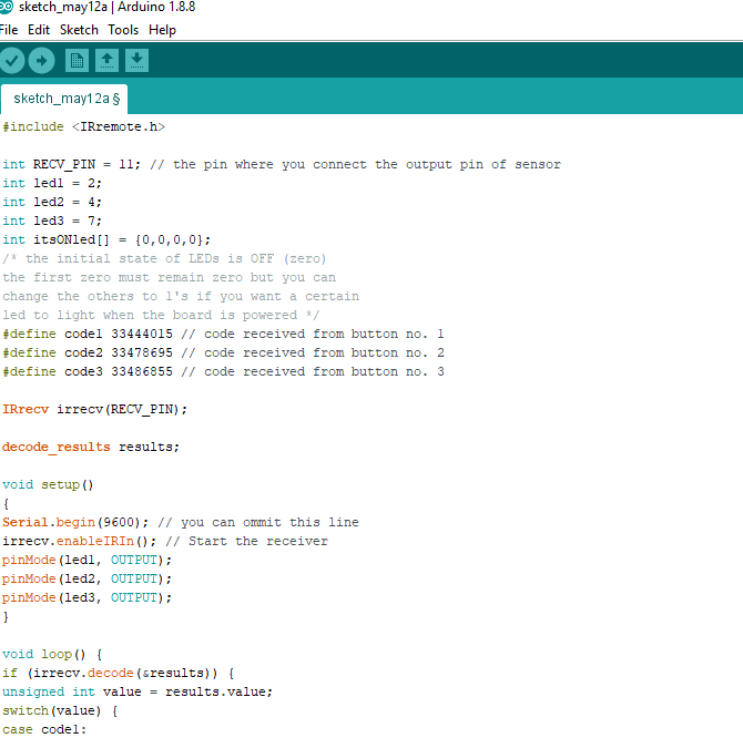
Copy and past this code to your Arduino IDE software and upload it.
#include <IRremote.h>
int IRpin = 11;
IRrecv irrecv(IRpin);
decode_results results;
void setup()
{
Serial.begin(9600);
irrecv.enableIRIn(); // Start the receiver
}
void loop()
{
if (irrecv.decode(&results))
{
Serial.println(results.value, DEC); // Print the Serial ‘results.value’
irrecv.resume(); // Receive the next value
}
}
Then go to serial monitor of the Arduino
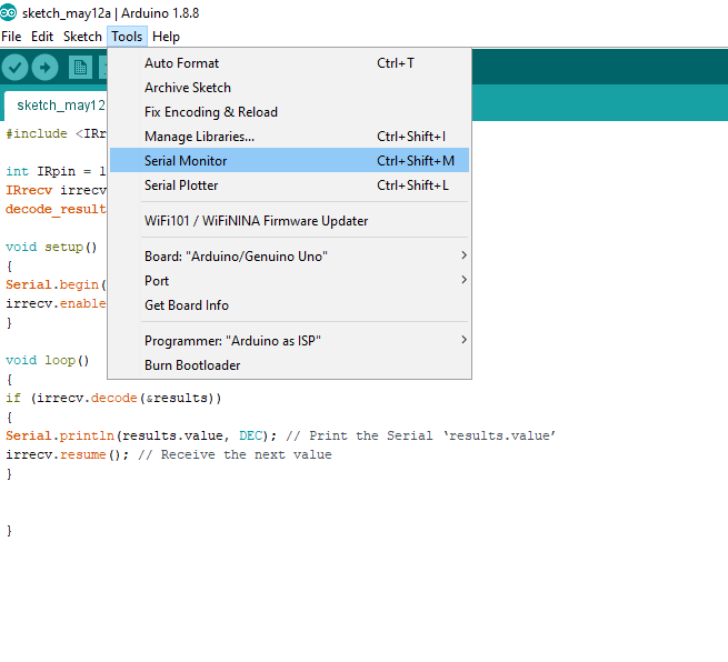
Press any key on the remote and save its binary number displaying in the serial monitor.

After getting all the binary numbers copy the code.

and connect led or relay driver in Arduino pin number 2,4,7 pins respectively

Copy this code and upload it to the Arduino
#include <IRremote.h>
int RECV_PIN = 11; // the pin where you connect the output pin of sensor
int led1 = 2;
int led2 = 4;
int led3 = 7;
int itsONled[] = {0,0,0,0};
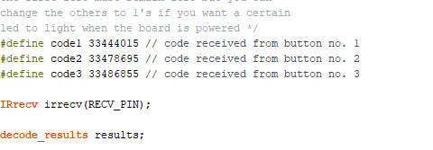
/* the initial state of LEDs is OFF (zero)
the first zero must remain zero but you can
change the others to 1's if you want a certain
led to light when the board is powered */
#define code1 33444015 // code received from button no. 1
#define code2 33478695 // code received from button no. 2
#define code3 33486855 // code received from button no. 3
IRrecv irrecv(RECV_PIN);
decode_results results;
void setup()
{
Serial.begin(9600); // you can ommit this line
irrecv.enableIRIn(); // Start the receiver
pinMode(led1, OUTPUT);
pinMode(led2, OUTPUT);
pinMode(led3, OUTPUT);
}
void loop() {
if (irrecv.decode(&results)) {
unsigned int value = results.value;
switch(value) {
case code1:
if(itsONled[1] == 1) { // if first led is on then
digitalWrite(led1, LOW); // turn it off when button is pressed
itsONled[1] = 0; // and set its state as off
} else { // else if first led is off
digitalWrite(led1, HIGH); // turn it on when the button is pressed
itsONled[1] = 1; // and set its state as on
}
break;
case code2:
if(itsONled[2] == 1) {
digitalWrite(led2, LOW);
itsONled[2] = 0;
} else {
digitalWrite(led2, HIGH);
itsONled[2] = 1;
}
break;
case code3:
if(itsONled[3] == 1) {
digitalWrite(led3, LOW);
itsONled[3] = 0;
} else {
digitalWrite(led3, HIGH);
itsONled[3] = 1;
}
break;
}
Serial.println(value); // you can ommit this line
irrecv.resume(); // Receive the next value
}
}
then replace the binary codes what you gets and upload it to your Arduino board.
you are done now press the respective button for on and off the LEDs or relay, you connected I the pin of Arduino.
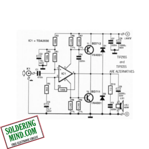
To control home appliances you needs to add a relay control circuit. The detailed circuit given below. As per the circuit connect all the components.

the initial state of LEDs remain ON. I want led certain
led to off when the board is powered. Please i need help.
int RECV_PIN = 11;
int led1 = 2;
int led2 = 4;
int led3 = 7;
int itsONled[] = {0,0,0,0};
#define code1 134772871
#define code2 134791231
#define code3 134763946
#define code5 4335
IRrecv irrecv(RECV_PIN);
decode_results results;
void setup()
{
Serial.begin(9600);
irrecv.enableIRIn();
pinMode(led1, OUTPUT);
pinMode(led2, OUTPUT);
pinMode(led3, OUTPUT);
}
void loop() {
if (irrecv.decode(&results)) {
unsigned int value = results.value;
switch(value) {
case code1:
if(itsONled[1] == 1) {
digitalWrite(led1, LOW);
itsONled[1] = 0;
} else {
digitalWrite(led1, HIGH);
itsONled[1] = 1;
}
break;
case code2:
if(itsONled[2] == 1) {
digitalWrite(led2, LOW);
itsONled[2] = 0;
} else {
digitalWrite(led2, HIGH);
itsONled[2] = 1;
}
break;
case code3:
if(itsONled[3] == 1) {
digitalWrite(led3, LOW);
itsONled[3] = 0;
} else {
digitalWrite(led3, HIGH);
itsONled[3] = 1;
}
break;
}
Serial.println(value);
irrecv.resume();
}
}
When powerd led didn’t get on
I did the project, and it work but the initial state of LEDs is in ON mood.I want the led to be in OFF mood when the board is powered. And it should only ON when the remote button is press. I need help.
#include
int RECV_PIN = 11; // the pin where you connect the output pin of sensor
int led1 = 2;
int led2 = 4;
int led3 = 7;
int itsONled[] = {0,0,0,0};
/* the initial state of LEDs is OFF (zero)
the first zero must remain zero but you can
change the others to (1)’s if you want a certain
led to light when the board is powered */
#define code1 134772871 // code received from button no. 1
#define code2 134791231 // code received from button no. 2
#define code3 134763946// code received from button no. 3
#define code5 4335
IRrecv irrecv(RECV_PIN);
decode_results results;
void setup()
{
Serial.begin(9600); // you can ommit this line
irrecv.enableIRIn(); // Start the receiver
pinMode(led1, OUTPUT);
pinMode(led2, OUTPUT);
pinMode(led3, OUTPUT);
}
void loop() {
if (irrecv.decode(&results)) {
unsigned int value = results.value;
switch(value) {
case code1:
if(itsONled[1] == 1) { // if first led is on then
digitalWrite(led1, LOW); // turn it off when button is pressed
itsONled[1] = 0; // and set its state as off
} else { // else if first led is off
digitalWrite(led1, HIGH); // turn it on when the button is pressed
itsONled[1] = 1; // and set its state as on
}
break;
case code2:
if(itsONled[2] == 1) {
digitalWrite(led2, LOW);
itsONled[2] = 0;
} else {
digitalWrite(led2, HIGH);
itsONled[2] = 1;
}
break;
case code3:
if(itsONled[3] == 1) {
digitalWrite(led3, LOW);
itsONled[3] = 0;
} else {
digitalWrite(led3, HIGH);
itsONled[3] = 1;
}
break;
}
Serial.println(value); // you can ommit this line
irrecv.resume(); // Receive the next value
}
}
I did the connection right but the binary number of the remote was not displaying in the serial monitor.
Please i need help.
you need to run the program and press the key on the remote