The Circuit Will Extend Life of Your Home Appliances, the Soft Starter circuit diagram – From the name it is mentioned that it will turn on the electrical home appliances smoothly. To know deeply you need to know how electrical equipment starts working when you are directly connecting to an AC source.
How An AC equipment start working
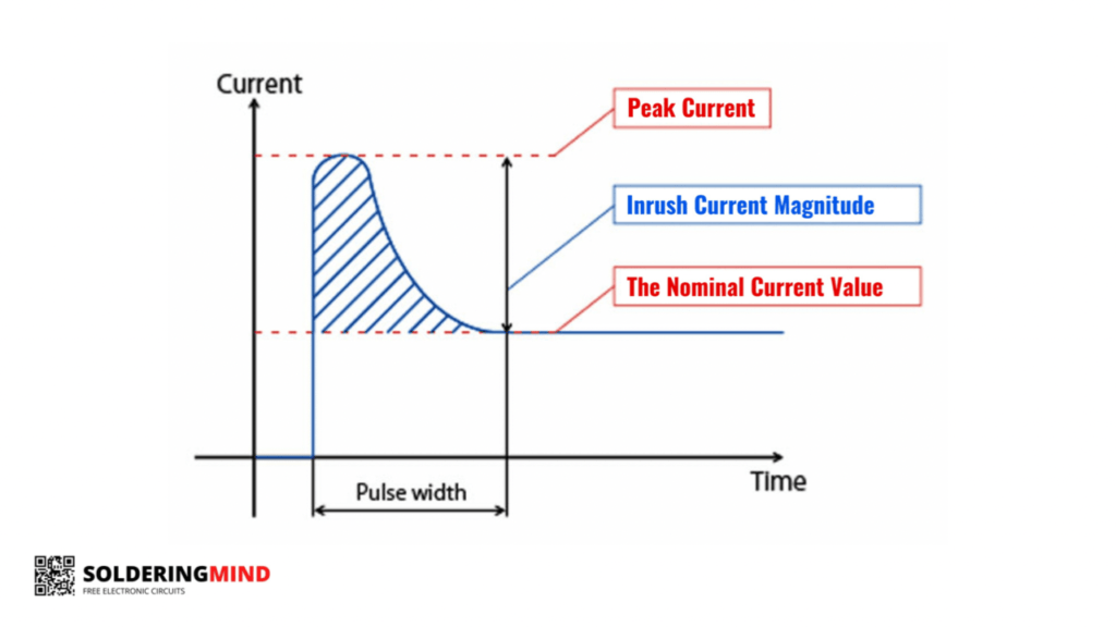
While normally an electrical device working is very simple to explain like plug and play… Yes if you are going to turn on a lamp in your room or a mixer grinder in the kitchen using a single switch. In that time a sudden brightness or high-speed startup of equipment is happening. This is due to the initial over current taking process. ( When you plug in a small fire on the socket )
This Initial peak of the Current will damage your electrical home appliances. Because of the large current, the internal components of electrical wiring get damaged or burned. The initial current is also known as the Inrush Current.
Some manufacturers add thermistors for surge protection. During long operations, the resistance increases due to the increasing temperature of the thermistor, and power loss occurs. So we designed a circuit to protect home appliances from Inrush current.
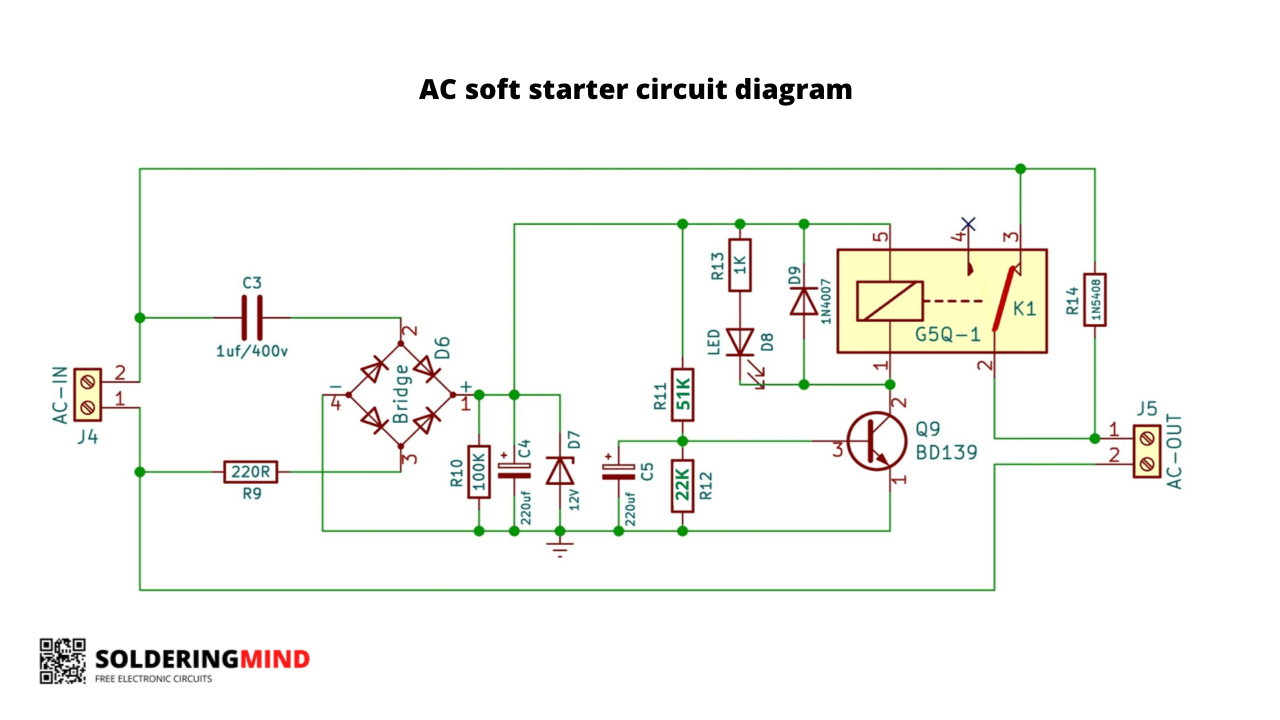
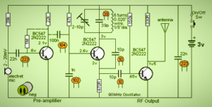
Soft starter circuit diagram
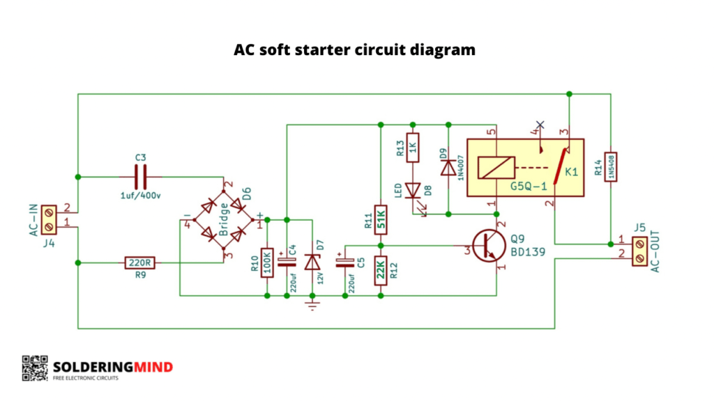
Working
while switching on AC input connected with the home appliances with a diode. This will limit the usage of huge current in the initial starting stage. At the same time, the circuit of the transformerless power supply gets to work. The 12v zener diode will stabilize the voltage to 12v.
C5 220uf capacitor gets charged slowly through the 51k ohm resistor. so it will delay on the second. When the capacitor is charged fully the transistor gets sufficient current to turn on the relay. Now the relay turns on and the loaded output gets full current directly from the AC mains by bypassing.

This is unsuitable for reactive (inductive, capacitive) loads. For those, it’s better to use a power resistor. Triac regulation is not suitable for inductive loads unless special measures are taken to prevent asymmetrical load current.
Jaką moc wytrzymuje tan układ?
w zależności od wartości znamionowej przekaźnika stykowego
Is the ground just for the circuit itself, separate from appliance ground?
Is. The ground the same as the neutral power line or is it just the internal ground to the circuit?
It’s just ground not connect to neutral
What is the used of 1n5408 ? Which side is the anode and cathode ?
Ac output side is cathode
What is the voltage of the relay ?
12v
R-14 is a resistor or 1N5408 diode?
Its diode 1n5408
so basically we are limiting the current by just allowing only half cycle of the ac sine wave to pass through?
It’s a diode