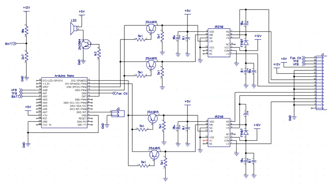
Today I am going to introduce a very good Arduino nano-based Electronics project of sine wave inverter. The Inverter circuit is a duplicate (like the exact match of pins ) of the EGS002 sine wave inverter driver board. So you can easily build and integrate this circuit in the place of the EGS002 sine wave driver board. The complete circuit diagram and also the raw Arduino code have to be published here.
Sine Wave Inverter Circuit Diagram
Arduino Programming Code
#include <avr/io.h>
#include <avr/interrupt.h>

/*
   SPWM_Nano_VFB3.ino

   Created : 8/11/2021
   Author  : solderingmind

   Left bridge used for fundamental signal (50Hz/60Hz), Right bridge for SPWM (10kHz carrier freq.)
   Sampling per Cycle
   ---> 10kHz/50Hz = 200
   ---> 10kHZ/60hz = 166
   Look Up table entries use only half cycles (identical positive and negative cycles)
   50 Hz --->  200/2 = 100 entries
   60 Hz --->  167/2 = 83 entries

   SPWM clock = fXTAL/freq. carrier = 16.000.000/10.000 = 1.600 clock.
   WGM mode 8 is used, so ICR1 = 1.600/2 = 800 clk
   Look up tables for a half cycle (100 or 83 entries), max value = 800 (100% duty cycle)is loaded into register ICR1.

  This code is for 50Hz !!!
  for 60Hz use the Lookup Table for 60Hz and use the code marked on the ISR(TIMER1_OVF_vect) !!!
*/

const byte      vfbPin = A0,
                tfbPin = A1,
                battPin = A2;
volatile double percentMod;
int             phs;

//---------------------------------Look Up Table for 50 Hz---------------------------------------
int lookUp1[] = {
  0,  25, 50, 75, 100, 125, 150, 175, 199, 223, 247, 271, 294, 318, 341, 363, 385, 407, 429, 450,
  470, 490, 510, 529, 548, 566, 583, 600, 616, 632, 647, 662, 675, 689, 701, 713, 724, 734, 744, 753,
  761, 768, 775, 781, 786, 790, 794, 796, 798, 800, 800, 800, 798, 796, 794, 790, 786, 781, 775, 768,
  761, 753, 744, 734, 724, 713, 701, 689, 675, 662, 647, 632, 616, 600, 583, 566, 548, 529, 510, 490,
  470, 450, 429, 407, 385, 363, 341, 318, 294, 271, 247, 223, 199, 175, 150, 125, 100, 75, 50, 25, 0
};


/*
//---------------------------------Look Up Table for 60 Hz---------------------------------------
int lookUp1[] = {
  0, 30, 60, 90, 120, 150, 179, 208, 237, 266, 294, 322, 349, 376, 402, 428, 453, 478, 501, 524,
  547, 568, 589, 609, 628, 646, 664, 680, 695, 710, 723, 735, 747, 757, 766, 774, 781, 787, 792, 796,
  798, 800, 800, 799, 797, 794, 790, 784, 778, 770, 762, 752, 741, 729, 717, 703, 688, 672, 655, 637,
  619, 599, 579, 558, 536, 513, 489, 465, 441, 415, 389, 363, 335, 308, 280, 252, 223, 194, 164, 135,
  105, 75, 45, 15, 0};
*/


void setup() {
  // Register initilisation, see datasheet for more detail.
  TCCR1A = 0b10110000;
  /*      10xxxxxx Clear OC1A/OC1B on compare match when up-counting. Set OC1A/OC1B on compare match when down counting
          xx11xxxx Set OC1A/OC1B on compare match when up-counting. Clear OC1A/OC1B on compare match when down counting.
          xxxxxx00 WGM1 1:0 for waveform 8 (phase freq. correct).
  */
  TCCR1B = 0b00010001;
  /*      000xxxxx
          xxx10xxx WGM1 3:2 for waveform mode 8.
          xxxxx001 no prescale on the counter.
  */
  TIMSK1 = 0b00000001;
  /*      xxxxxxx1 TOV1 Flag interrupt enable. */
  ICR1   = 800;      /* Counter TOP value (at 16MHz XTAL, SPWM carrier freq. 10kHz, 200 samples/cycle).*/
  sei();             /* Enable global interrupts.*/
  DDRB = 0b00011110; /* Pin 9, 10, 11, 12 as outputs.*/
  PORTB = 0;

  pinMode(13, OUTPUT);
  pinMode(8, OUTPUT);
  pinMode(7, OUTPUT);
  pinMode(2, INPUT_PULLUP);

  percentMod = 0.01;
  for (int i = 0; i < 75; i++) {              // Soft Start
    percentMod = percentMod + 0.01;
    delay(20);
  }
}


void alarmIndication(int alarm)
{
  TCCR1A = 0;                             // shutdown SPWM output
  TIMSK1 = 0;
  PORTB &= 0b11100001;
loopX:
  for (int i = 0; i < alarm; i++) {
    digitalWrite(7, HIGH);                // turn ON LED and Buzzer
    digitalWrite(13, HIGH);
    delay(200);
    digitalWrite(7, LOW);                 // then turn OFF
    digitalWrite(13, LOW);
    delay(200);
  }
  delay(1000);
  goto loopX;                           //never ending story... until reset
}

void feedBackTest(float vfbIn, int tfbIn, int battIn) {
  long alrm;
  static int alrmCnt;

  if (digitalRead(2) == LOW) return;
  if (phs != 1) return;

  alrm = constrain(vfbIn, 462, 660);
  if (alrm !=vfbIn) alrmCnt++; else alrmCnt=0;
  if (alrm == 462 && alrmCnt >= 150) alarmIndication(2);        // underVoltage @ 2.5V --> 2.75 / 5 x 1023 = 562
  if (alrm == 660 && alrmCnt >=15) alarmIndication(3);          // overVoltage @ 3.15V --> 3.15 / 5 x 1023 = 645
  if (tfbIn >= 924) alarmIndication(4);                         // over temp @ 80C --> 10k/(10k + 1.068k) x 1023 =924
  if (battIn <= 457) alarmIndication(5);                        // low batt @ 10.5V --> (2k7/12.7k x 10.5) / 5 x 1023 = 457
  if (tfbIn >= 725 && digitalRead(8) == LOW)  digitalWrite(8, HIGH);  // fan ON @45C --> 725
  if (tfbIn <= 679 && digitalRead(8) == HIGH) digitalWrite(8, LOW);   // fan OFF @40C --> 679

}

void loop() {
  static int vfbValue;
  static int vfbValue1;
  static int vfbRise = 0;
  static float vMax;
  float alrm = 0;
  static int alrmCnt = 0;
  float ampDiff;

  if (phs = 1) {
    vfbValue1 = vfbValue;
    vfbValue = analogRead(vfbPin);                              // vfbPin = 0 to 5V ---> vfbValue = 0 to 1023

    if (vfbValue > vfbValue1 && vfbValue > 200) vfbRise = 1;     //check for positif cycle, bigger than noise
     if (vfbValue < vfbValue1 && vfbRise == 1) {                 // maximum vfb value reached
      vfbRise = 0;
      vMax = vfbValue1;
      ampDiff = 614 - vMax;
      if (ampDiff > 5 || ampDiff < -5) {
        percentMod = percentMod + (ampDiff / vMax);               // voltage correction
        if (percentMod > 0.97) percentMod = 0.97;               // limit duty cycle to 97%
      }

     feedBackTest(vMax, analogRead(tfbPin), analogRead(battPin));
      vMax = 0;
    }
  }
}


/*---------------------------------------------------------------------------------------------------------*/
ISR(TIMER1_OVF_vect) {
  static int num;
  static int  ph;
  static int dtA = 0;
  static int dtB = 5;

  if (num >= 99) {    // <------------------ 50 Hz !!!
//  if (num >= 82) {    // <------------------ 60 Hz !!!
    if (ph == 0) {         // OC1A as SPWM out
      TCCR1A = 0b10110000; // clear OC1A, set OC1B on compare match
      dtA = 0;             // no dead time
      dtB = 5;            // adding dead time to OC1B
    } else {
      TCCR1A = 0b11100000; // OC1B as SPWM out
      dtA = 5;
      dtB = 0;
    }
    ph ^= 1;
  }
  OCR1A = int(lookUp1[num] * percentMod) + dtA; // SPWM width update
  OCR1B = int(lookUp1[num] * percentMod) + dtB; // note: 0.7 used to reduce inveter output voltage

  num++;
  if (num >= 100) {                   // toggle left bridge (50Hz) !!!
//  if (num >= 83) {                   // toggle left bridge (60Hz) !!!
    delayMicroseconds(60);
    if (ph == 1) {
      digitalWrite(12, LOW);
      digitalWrite(11, HIGH);
      phs = 1;
    } else {
      digitalWrite(11, LOW);
      digitalWrite(12, HIGH);
      phs = 0;
    }
    num = 0;
  }
}

Sir you have added the schematic of 1 circuit but what about the other one which contain the mosfets ?
power stage building is very easy so i excluded from this post
please thank you for the good project you have shire with us your followers please can you send me a code 23.4khz please i need that for my small project or can you tell me where in the code to change in the code to obtain 23.4khz thank you hope to hear from you soon.
Is it’s Sine wave inverter program code lcd display including
Hi sir I m using Atmega32 and programing in Bascom avr to generate spwm 50hz signal on oc1a and oc1b pin 18,19
I generate table with Sine smart software it’s work fine but difference between both oc1a and oc1b, one output is 1.56v and the other is 3.4v kindly help me
Hello, is it possible to go from 10kHz to 23.4kHz like the egs002 has?
Yes its possible Ned to change codes
Bună ziua, este posibil să treceți de la 10 kHz la 23,4 kHz așa cum are egs002?
Hello, is it possible to switch from 16 khz to 23.4 khz as egs002 has?
Pls I need your whatapp number
Contact me through telegram @blockchainvalidator