Hi hello, friends again will come back to our new article about a fully advanced high-frequency inverter circuit. This fully automatic inverter will give the indications of high voltage range and low voltage range and overload indication along with power temperature indication. In those conditions the inverter will go turn off and again turn on if the condition is restored and start to work ok is the output.
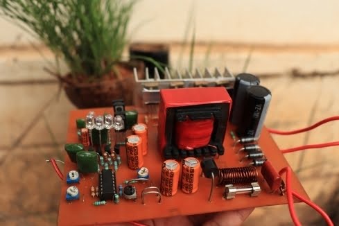
The inverter will deliver the power output of 500 Watts. if you want more power output you need to increase the number of MOSFETs at the number of high-frequency transformers. In this sir cute I using a medium-sized transformer, which will easily get from the old televisions. the windings of the transformer and the fully secured details given below. So please note that read all the paragraphs properly for a better understanding about the fully automatic inverter.
Circuit Diagram
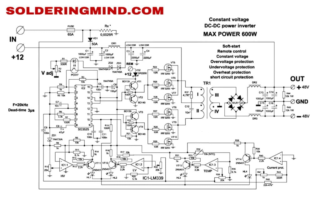
NOTE: Some changes done on PCB it’s not showing in the circuit diagram. Here the basic circuit you will get.
How automatic inverter works
The working of this automatic inverter is very easy to understand. If you think the circuit is very complicated, no. It’s very simple and easy to understand everyone. The circuit working based on 2 integrated circuits. The sg3525 and lm339. Sg3525 is used as an inverting signal generator and Lm339 is used for cut off when in such conditions of
- High Voltage
- Low voltage
- Overload and short circuit
- High temperature
To adjust these parameter you can get 4 potentiometer. Adjust the potentiometer and set the cut off value you want. These cut off circuit will shut off inverter automatically.
Automatic shut off Feature
The power inverter automatic cut off working based the desired cut off range you are already set by adjusting the pot. The high voltage range of 15 v or above the IC get activated and start to light led representing the high voltage range. When the voltage goes down below 10v the low voltage indicates.
As like the overload and over temperature protection works.


Thanks brother
You are welcome my friend
Gracias muy bien explicado mil bendiciones
Wow welcome
The Zener used by REM.
Please tell me its value
Sagheer Ahmad from Pakistan
thanks buddy
Where I can buy your inverter boards