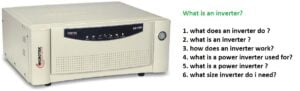
The circuit is based on high-frequency pulses produced by the sg3525 ic. Briefly explain the high-frequency inverter using the principle of pulse width modulation. Converting DC to AC with the help of a switching device like MOSFET and then again it will be converted into DC by the process of rectification by the high-frequency techniques. we are doing this to get the compactness of the device and become economical. There is a lot of application such as laptop charger commercial lighting and more.
Introduction

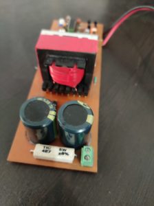
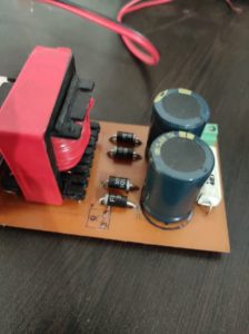
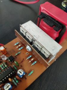
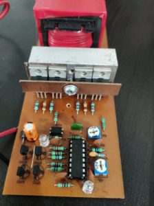
We have using SG 3525 which will set the oscillator frequency also by the pulse width modulation so we can get control the constant voltage. I have also using the forest core transformer because the normal transformer is not suitable for high-frequency operation. advantages of the forest for that reduces the losses and the cost is much less you are using IC SG 3525 for the purpose of generating 50-kilohertz frequency.
Working Principle
when the supply is given to pin number 13 and in number 15 the circuit capacitor connected to pin number 8 of the IC starts charging to provide starting of the IC and then it starts to work. Discipline from the battery is to be provided to the pin number 13 and the PIN number 15 as well as the center tap transformer.
Connecting the positive and the negative terminal to the IC the power output pin number 11 and 14 to generate the pulse to drive the most points in the most gets to drive the palace from the PIN number 11 and number 14 they start to switch. Due to the sitting action, the current from the battery flow in the primary of the transformer and will change and due to the magnetic coupling the action to get induced in the secondary winding.
Then we will get the AC supply which will be rectified through the ultra-fast diode. After filtering we will get the DC voltage supply output. the signal is then feedback to the inverting terminal of the error amplifier which will compare the inverting input with the noninverting input and the output of the error amplifier is given to the input of the trigger. Controlling the output voltage.

Thank you for this circuit. Pls I the drawing of the circuit diagram.
Será que você poderia tá liberando o esquemario do circuito por favor senhor ……
Congratulations, but the Digital Inverter Circuit Diagram is missing, please do us this grace, thank you.
Mil gracias por tu gran aportación estoy realizando la fabricación del inversor y solo faltaría ponerlo a prueba
Please give me a diagram. What is the output voltage 220 ?
Please how many turn with primary and secondary
Is there a component list.
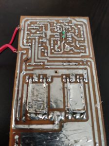
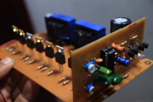
You pcb looks very clean! I like the layout.
You should translate your English back into the original language. Some words did not survive translation like forest transformer. Forest is a large number of trees. It has nothing to do with transformers.
HAHA IT IS A WRITING MISTAKES
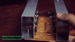
Can you please tell me a mosfet that can drive 2000w load
use irf1404 or irf3205
What is the maximum and minimum output voltage of this inverter? And how many watts will its power be?
500 watts 220v