Want to build a fun and easy electronics project? Build a simple police siren circuit using two 555 timer IC. The circuit diagram and its connection details are explained here. This is a very basic circuit for electronic hobbyist. a 50K preset is given to adjust the frequency of the sound. You can use connect a mini 8 ohms speaker for getting the siren sound.
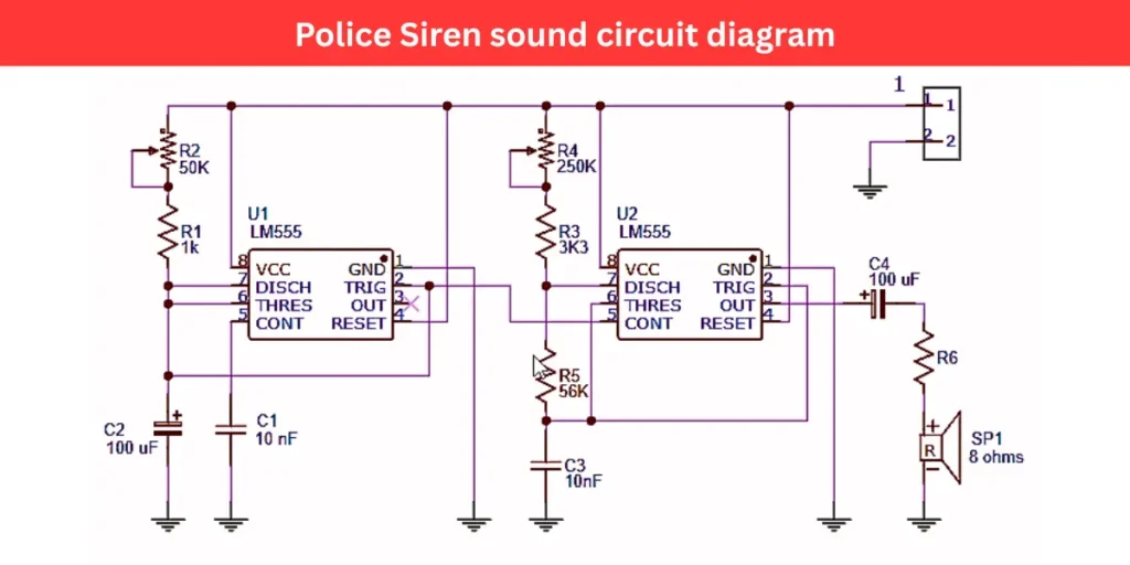
Circuit Diagram
Components Required
| Component | Value/Type | Quantity |
|---|---|---|
| U1, U2 | LM555 | 2 |
| R1 | 1 kΩ | 1 |
| R2 | 50 kΩ (Variable) | 1 |
| R3 | 3.3 kΩ | 1 |
| R4 | 250 kΩ | 1 |
| R5 | 56 kΩ (Variable) | 1 |
| R6 | 0.1 – 1 ohms | 1 |
| C1 | 10 nF | 1 |
| C2 | 100 µF | 1 |
| C3 | 10 nF | 1 |
| C4 | 100 µF | 1 |
| SP1 | 8 Ω Speaker | 1 |
| Power Supply | 9V or 12V DC | 1 |
Connection and Working
This police siren sound circuit uses two LM555 timer IC and it is configured in astable mode. The circuuit will generate a modulated audio tone that mimics the sound of a police siren.
The first timer IC is set up to produce a low frequency oscillation. Its output is connected to pin 5 of the second 555 timer IC, which generates a high frequency tone. The varying voltage from first IC modulates the frequency of second IC. This will creating a siren like up and down tones. The resistors R1 (1k), R2 (50k variable), and capacitor of 100µF will determine the oscillation frequency of first IC.
Capacitor 10nF is connected to pin 5 of U1 to stabilize its operation. The output from pin 2 of U1 is fed into the control voltage pin of U2, influencing its oscillation. U2’s frequency is set by R3 (3.3k), R4 (250k), R5 (56k), and capacitor C3 (10nF). The modulated audio signal is then passed through a coupling capacitor (C4, 100µF) and a current-limiting resistor (R6) to an 8-ohm speaker (SP1), which produces the audible siren sound.