Introduction
A continuity tester is used to check whether an electrical path or wire has good conductivity. This tester helps identify whether a connection, wire, or component is broken or is properly conducting electricity. In this article, a simple continuity tester circuit with a buzzer is presented to help identify broken wires or faulty connections.
What Is Continuity Testing?
The Continuity testing means the current can conduct through the wire or component without break. The open circuit continuity is zero and closed circuit a good continuity.
- Good continuity means the circuit is complete
- No continuity means the wire is broken, faulty joint or damaged component
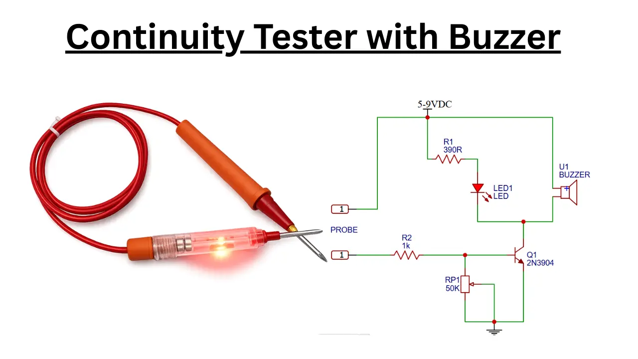
Continuity Circuit diagram

Circuit Diagram Overview
This continuity tester circuit is working in 5-9V dc supply. You can use a %V mobile charger or 9vDC supply to power the circuit. The 2N3904 is the main component in this circuit. This is a medium power NPN transistor acts as a switch. When the testing probe touches the conducting path, the transistor turns ON and buzzer starts to sound and also gives an LED for visual representation.
Components Used to Build This Circuit
- 2N3904 NPN Transistor
- LED
- Piezo Buzzer
- 390Ω Resistor
- 1kΩ Resistor
- 50kΩ Potentiometer
- Battery (5V–9V)
- Testing Probes
Working Principle
There are two probes are available to check the continuity of wire or component. Connect the probes to the unknown path of connection. If the connected path has good continuity means there is no break or fault in the path. The good continuity situation charges passing through the path and reaches to the NPN transistor base pin.
When the charge reaches to the base of the transistor, will turn ON the buzzer and LED. Which will gives the visual and audible ways of proper continuity of the connected path. If there is no continuity means the transistor remains OFF and both indicators stay inactive.
Role of the Potentiometer
The 50kΩ potentiometer controls the sensitivity of the tester. The higher sensitivity is used to test very low resistance paths. The sensitivity can be adjustable by rotating near to the ground connection.
Advantages of This Circuit
- Simple and low cost circuit with few number of electronic components.
- Dual indication using LED and buzzer for light and sound.
- The circuit is portable and battery powered.
- You can adjustable sensitivity
- No microcontroller required
Applications of This Circuit
- Testing wires and cables
- Checking PCB tracks
- Identifying broken connections
- Testing switches and fuses
- Educational electronics projects
Conclusion
This continuity tester circuit is a simple electronic circuit that can be easily built by any electronics enthusiast. Only a few electronic components are used in this circuit, making it low cost. Using this simple tester circuit, you can check the continuity of any connections or wires.