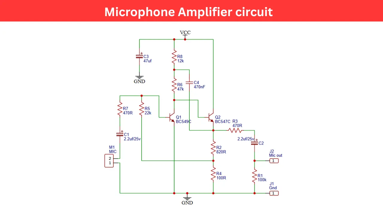
A microphone amplifier is an essential part of any audio system, designed to boost the weak electrical signal from a microphone to a level suitable for further amplification or recording. Here i am sharing a two stage transistor based microphone amplifier using BC549C and BC547C NPN transistors.
Components Required
| Component | Value | Quantity |
|---|---|---|
| Q1 | BC549C | 1 |
| Q2 | BC547C | 1 |
| R1 | 100kΩ | 1 |
| R2 | 820Ω | 1 |
| R3 | 470Ω | 1 |
| R4 | 100Ω | 1 |
| R5 | 22kΩ | 1 |
| R6 | 47kΩ | 1 |
| R7 | 470Ω | 1 |
| R8 | 12kΩ | 1 |
| C1, C2 | 2.2µF/25V | 2 |
| C3 | 47µF | 1 |
| C4 | 470nF | 1 |
| M1 | Microphone | 1 |
| J2 | Mic Output | – |
Microphone Amplifier Circuit Diagram
Working Principle
In this circuit a microphone (M1) is connected and which converts the sound waves into weak electrical signals. These signals are AC in nature and need amplification before they can be processed further.
The microphone output passes through the capacitor C1 of 2.2µF and which will removes any DC component, So this allowing only the Audio AC signal to pass.
The signal from the microphone is enters the base of transistor Q1, which is serves as the first amplifier stage. The R5 and R7 form a voltage divider network to bias the transistor properly. The Resistor R4 is an emitter resistor that stabilizes the transistor’s operation.
The amplified signal at the collector of Q1 is then fed into the second transistor stage via capacitor C4 value of 470nF, which is acts as a coupling capacitor.
This stage provides initial voltage amplification and ensures that the next stage receives a clean, amplified signal. The signal from Q1 is further amplified by Q2, which operates as the main amplifier stage.
The resistor R2 and R3 set the gain of this stage. Capacitor C3 (47µF) acts as a power supply filter to prevent noise. The resistor R6 and R8 bias the transistor properly for linear amplification.
The amplified output signal is then sent to the output terminal through capacitor C2 of 2.2µF, which blocks the DC and allows only the AC audio signal to pass. This output signal is clean and amplified form and it is used for further amplification using power amplifiers.
Power Supply for Circuit
The circuit operates from a single DC power supply. The exact voltage can range between 6V to 12V, depending on the required amplification and transistor specifications. C3 (47µF) filters out power supply ripples to ensure a clean, noise free signal.
Audio Output and Performance
The final output, taken from J2 (Mic Out), provides a sufficiently amplified audio signal that can be fed into,
- A power amplifier
- Audio recorder
- Mixer console
- Audio processing circuit
Applications
- DIY audio projects
- Voice recorders
- Intercom systems
- Audio preamplifiers
- Hearing aid circuits
- Acoustic sensor systems
Tips for Better Performance
- Use shielded cables for input and output to minimize the hum and noise.
- Place the microphone away from high the frequency interference sources.
- Ensure proper grounding to reduce feedback.
- Use a low noise power supply for best results.