2SD965 is also marked as D965 on the transistor’s surface; both are the same. The D965 is an NPN transistor that comes in a TO-92 package. In this article, I’m sharing the information’s of D965 transistor pinout, equivalent transistor for replacement, and its specifications.
What is the 2SD965 Transistor?
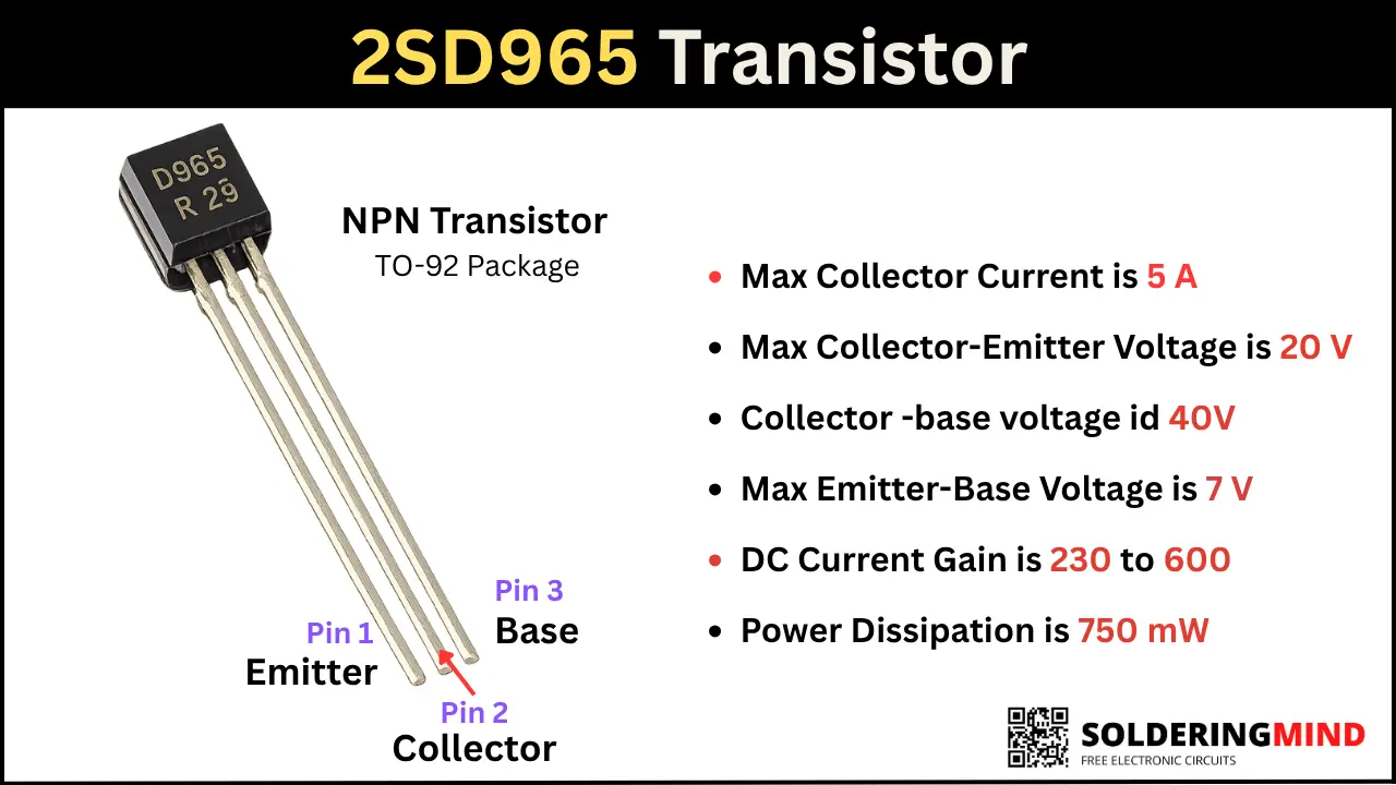
2SD965 is a BJT NPN transistor that comes in TO-92 plastic packaging. It is a low-voltage and high-current handling electronic component. This transistor can handle 20V of collector-emitter voltage and 5A collector current. In Stroboscope circuits and amplifier driver stage this transistors are using.
2SD965 Pinout Diagram
2SD965 Pin Configuration
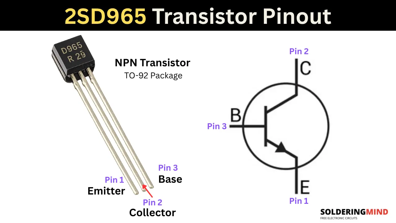
Hold the transistor pins are pointing downward and the labelled number is facing you, then count the pin number from left to right and the pins will be,
- Emitter (E): Pin 1
- Collector (C): Pin 2
- Base (B): Pin 3
2SD965 Specifications
- Transistor Type: NPN
- Max Collector Current is 5 A
- Max Collector-Emitter Voltage is 20 V
- Collector -base voltage id 40V
- Max Emitter-Base Voltage is 7 V
- DC Current Gain is 230 to 600
- Power Dissipation is 750 mW
How the 2SD965 Transistor Works
The 2SD965 is a NPN BJT transistor, it works as current controller switch or signal amplifier. The three terminals of emitter, collector, and base. The N type layer is sandwiching P type layer. In this NPN transistor, the electrons flow from the emitter to the collector region.
This electron movement is only occurs if the base region gets enough threshold voltage. Small voltage reached the base pin, and the transistor will turn ON and conduct current through the collector to emitter, the current can be handled up to 5A.
2SD965 Transistor Equivalent and Replacement
You can use this direct replacement of KSD5041RTA, 2SD966, ZTX869, ZTX851 and ZTX849. Always check pin configuration and specifications before replacing in the circuit board.
How to Test the 2SD965 Transistor Using a Multimeter
Set your multimeter to diode mode and connect the probe based on the data given in the table below to check the transistor is good or bad.
| Red Probe On | Black Probe On | Expected Reading | Status |
|---|---|---|---|
| Base (Pin 3) | Emitter (Pin 1) | 0.55V–0.75V | ✅ Good |
| Base (Pin 3) | Collector (Pin 2) | 0.55V–0.75V | ✅ Good |
| Emitter (Pin 1) | Base (Pin 3) | OL (Over Limit / 1) | ✅ Good |
| Collector (Pin 2) | Base (Pin 3) | OL (Over Limit / 1) | ✅ Good |
| Collector (Pin 2) | Emitter (Pin 1) | OL (Over Limit / 1) | ✅ Good |
| Emitter (Pin 1) | Collector (Pin 2) | OL (Over Limit / 1) | ✅ Good |
Typical Applications of the 2SD965 Transistor
- In camera flasher units this transistor is using because of high current handling and faster switching speed.
- In low frequency audio circuits this transistor are commonly using.
- For high current switching circuits this transistor is a good choice because it can handle up to 5A current.