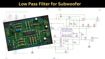
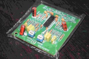
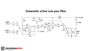
Are you looking for a high quality Subwoofer low pass filter circuit. This UPC4570HA IC based Low pass Circuit diagram is from Yamaha audio amplifier. This is a perfect circuit for 18Hz to 160Hz frequency filtering. Interested in low frequency sound response, you can use this circuit as a reference and build one for you.
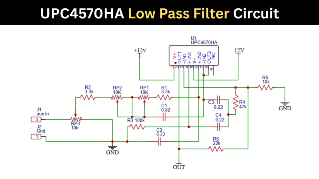
UPC4570HA IC Low pass Filter Circuit
Components Required
| Sl No | Component | Value / Part Number | Quantity |
|---|---|---|---|
| 1 | IC | UPC4570HA Dual Operational Amplifier IC | 1 |
| 2 | Resistor R1 | 3.3kΩ | 1 |
| 3 | Resistor R2 | 3.3kΩ | 1 |
| 4 | Resistor R3 | 100kΩ | 1 |
| 5 | Resistor R4 | 47kΩ | 1 |
| 6 | Resistor R5 | 10kΩ | 1 |
| 7 | Resistor R6 | 22kΩ | 1 |
| 8 | Potentiometer RP1 | 10kΩ | 1 |
| 9 | Potentiometer RP2 | 10kΩ | 1 |
| 10 | Potentiometer RP3 | 10kΩ | 1 |
| 11 | Capacitor C1 | 0.82µF | 1 |
| 12 | Capacitor C2 | 0.22µF | 1 |
| 13 | Capacitor C3 | 0.22µF | 1 |
| 14 | Capacitor C4 | 0.22µF | 1 |
| 15 | Audio Input Connector | AUX Input Jack | 1 |
| 16 | Power Supply | +12V Dual Supply | 1 |
| 17 | Output Terminal | Audio Output Connector | 1 |
Power Supply Requirement
This UPC4570HA IC based subwoofer filter board needs a 12V Dual power supply. You can use 1A 12-0-12 transformer to power the circuit. Use proper rectifier and capacitor for reducing the DC noise generated while 12V Ac to DC conversion.
Potentiometer Connection
In the circuit RP1 and RP2 is dual stereo potentiometer. The connection should be proper then only the working will be nice. The two potentiometer is connected series and its center pin is connected common to the other 10K potentiometer center pins.
Applications
- Suitable for Car subwoofer amplifier.
- Home audio system.