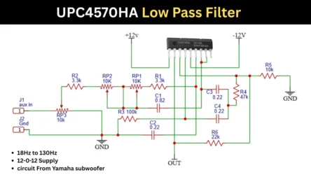
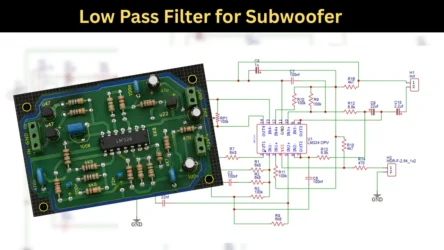
Low-pass filter circuits are available at a cheap price in all electronics shops. The low-pass filter boards have different properties; some people don’t like a single IC filter board. Some like small filter boards. But the electronic experts look like they are perfect for the working of those boards, not the designs. Actually, if you are planning to buy these boards from the market, you need to know something about them. How it is working and why these boards are needed in the power amplifier board to drive the subwoofers.
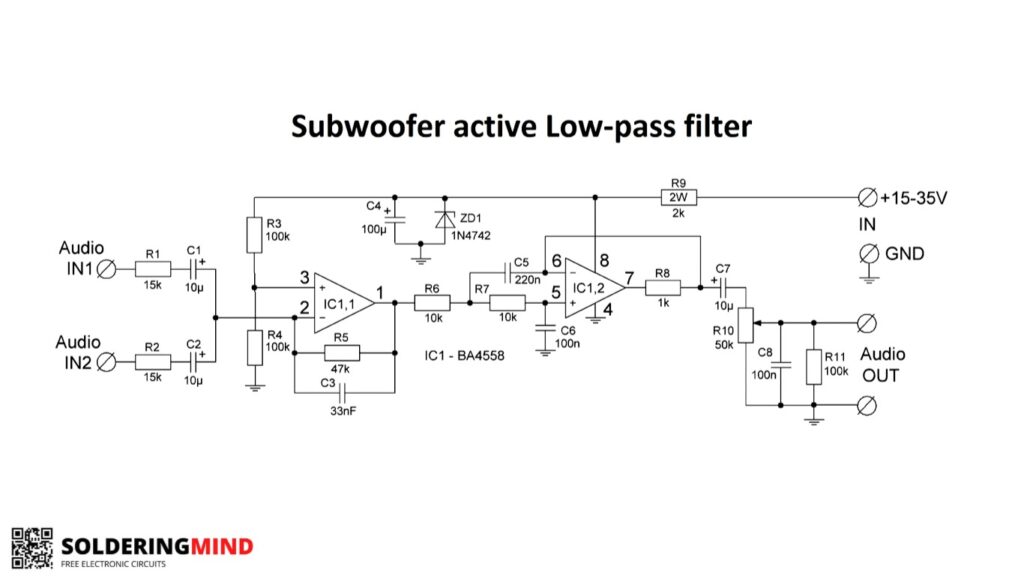
BA4558 (4558 IC) Low Pass Filter Circuit Diagram
The low pass filter board – from the word, The function of the electronic board is mentioned. Low pass means the lower frequency in terms of audio. The audio signals we can hear from the frequency range of 20 Hz to 20 kHz. The subwoofer filter board works in the frequency range of 15 Hz to 150 Hz. This low-frequency sound makes your subwoofer create a booming sound. So the best subwoofer board will give the super depth of the audio.
Components Required to Assemble This Circuit
| Sl. No. | Component | Reference | Value / Part No. | Quantity |
|---|---|---|---|---|
| 1 | Dual Op-Amp IC | IC1 | BA4558 | 1 |
| 2 | Resistor | R1, R2 | 15 kΩ | 2 |
| 3 | Resistor | R3, R4 | 100 kΩ | 2 |
| 4 | Resistor | R5 | 47 kΩ | 1 |
| 5 | Resistor | R6, R7 | 10 kΩ | 2 |
| 6 | Resistor | R8 | 1 kΩ | 1 |
| 7 | Resistor | R9 | 2 kΩ | 1 |
| 8 | Potentiometer | R10 | 50 kΩ | 1 |
| 9 | Resistor | R11 | 100 kΩ | 1 |
| 10 | Capacitor | C1, C2 | 10 µF | 2 |
| 11 | Capacitor | C3 | 33 nF | 1 |
| 12 | Capacitor | C4 | 100 µF | 1 |
| 13 | Capacitor | C5 | 220 nF | 1 |
| 14 | Capacitor | C6, C8 | 100 nF | 2 |
| 15 | Capacitor | C7 | 10 µF | 1 |
| 16 | Zener Diode | ZD1 | 1N4742 | 1 |
| 17 | Power supply | — | +15 to +35 V DC | 1 |
The single 4558 op-amp IC is used for this circuit. The circuits need 15 V DC to start working. Don’t worry, it will also work in 12V DC. The filter circuit is a single power supply based one. So you can easily use this for a car subwoofer amplifier. Very few components and a low cost to build this one. The IC is named BA4558. If it is impossible to find the same, not a problem; you can use any 4558 op-amp IC.
Provide the audio input from the audio source and turn on the circuit. The filtered signal will get in the output section. You can connect the output to the subwoofer amplifier input section. So I hope you like this circuit and project.
What does the Zener diode do here?
The 1N4742A is a 12V Zener diode. This Zener diode is connected in reverse bias to the IC input supply rail of the positive supply. This ZD1 Zener diode is used to control and stabilize the input voltage.
If you provide the supply voltage of 15 V to 35 V DC through the 2K resistor, the Zener maintains the voltage of 12 V to the IC. This will not change if you vary the input supply voltage.
Input and Gain Section
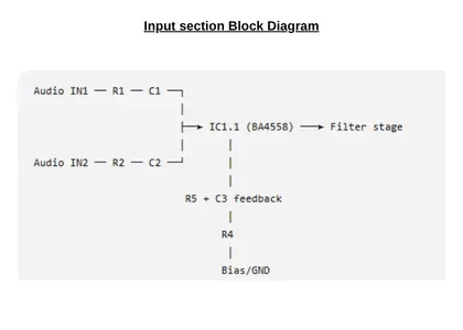
In the input section, stereo input is provided through a 15K resistor. This input audio is marked as IN1 and IN2. The 10uf electrolytic capacitor is also connected through the line to filter the DC voltage and allows the passage of the AC signal to the IC. The stereo signals are combined and feed into the IC for initial amplification.
The resistors of 47K and 100K provide the feedback and determine the gain. The 33 nF makes the gain depend on the frequency. The high-frequency signal is cut off, and the low-frequency signal gets amplified. This helps to give pure low-frequency audio output.