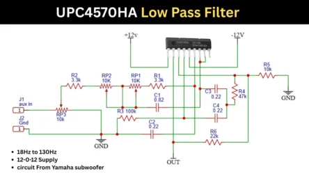
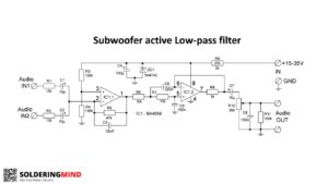
In market most of the available sub filter boards are working on 12V dual power supply. If you want to build a small subwoofer amplifier which is operated in single power supply or 12V battery connection you need a single power supply based Low Pass Filter for Subwoofer. This article shares the sub filter using LM324 IC with its circuit diagram.
Low Pass Filter for Subwoofer Circuit Diagram
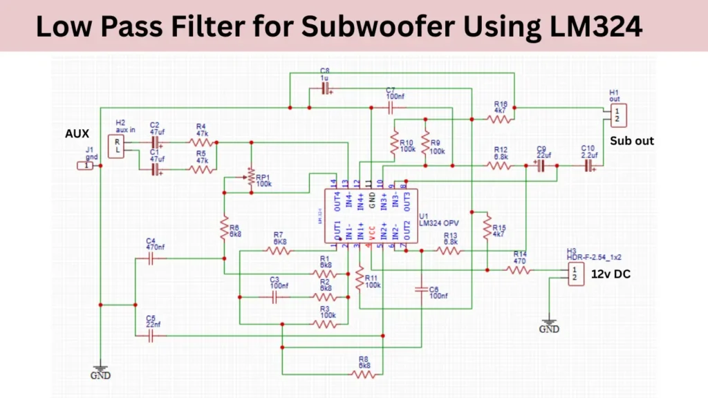
Components Required
| Sl. No | Component Type | Value / Specification | Quantity |
|---|---|---|---|
| 1 | IC | LM324 | 1 |
| 2 | Resistor | 47K | 2 |
| 3 | Resistor | 100K | 6 |
| 4 | Resistor | 6.8K (6K8) | 6 |
| 5 | Resistor | 4.7K (4K7) | 2 |
| 6 | Resistor | 470Ω | 1 |
| 7 | Capacitor (Electrolytic) | 47µF | 3 |
| 8 | Capacitor (Electrolytic) | 22µF | 1 |
| 9 | Capacitor (Electrolytic) | 100µF | 1 |
| 10 | Capacitor (Ceramic) | 100nF | 3 |
| 11 | Capacitor (Ceramic) | 22nF | 1 |
| 12 | Terminal Block | Input (IN, GND) | 1 |
| 13 | Terminal Block | Output (OUT) | 1 |
| 14 | Terminal Block | Power (12V+, GND) | 1 |