TIP127 is a PNP Darlington transistor. This transistor is built with a monolithic Darlington pair. In this article, I’m sharing the information’s of TIP127 transistor pinout, equivalent, specifications, and its uses.
What is the TIP127 Transistor?
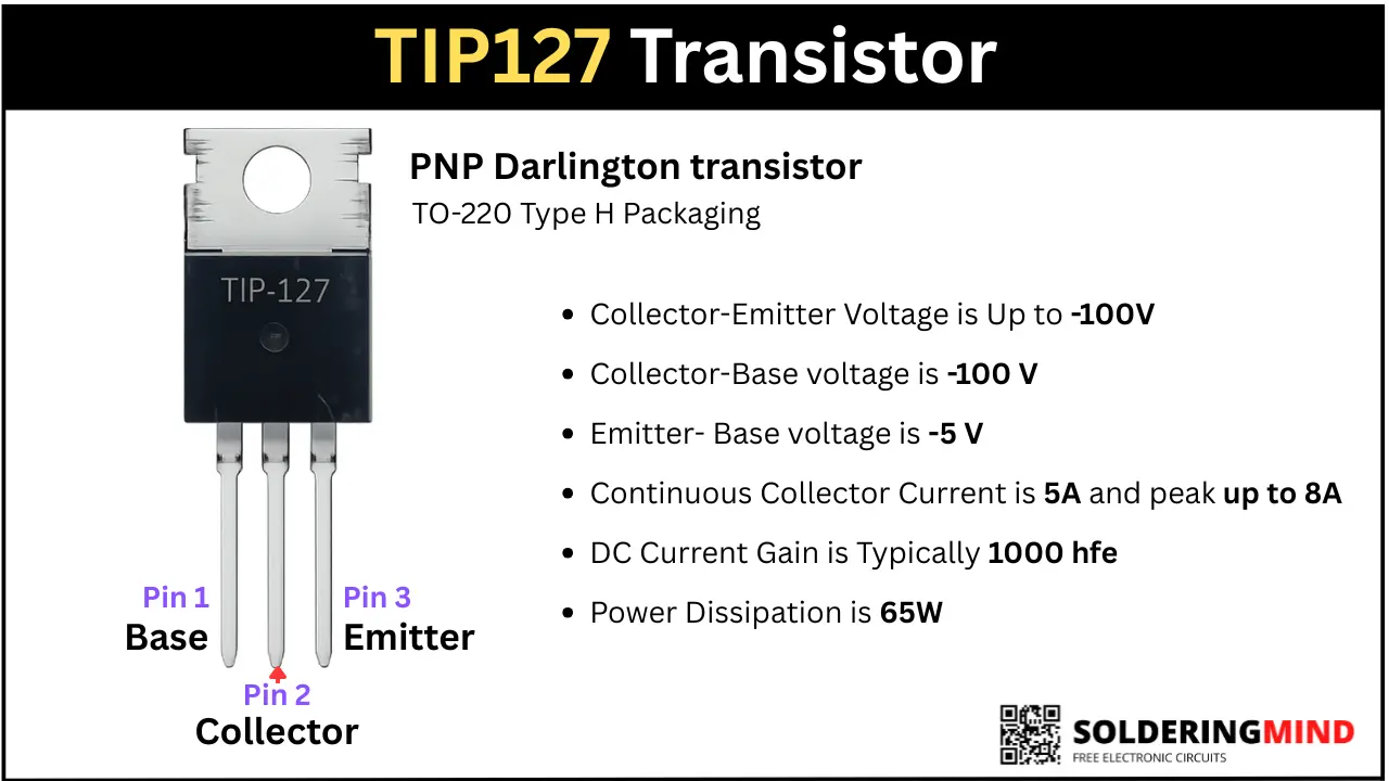
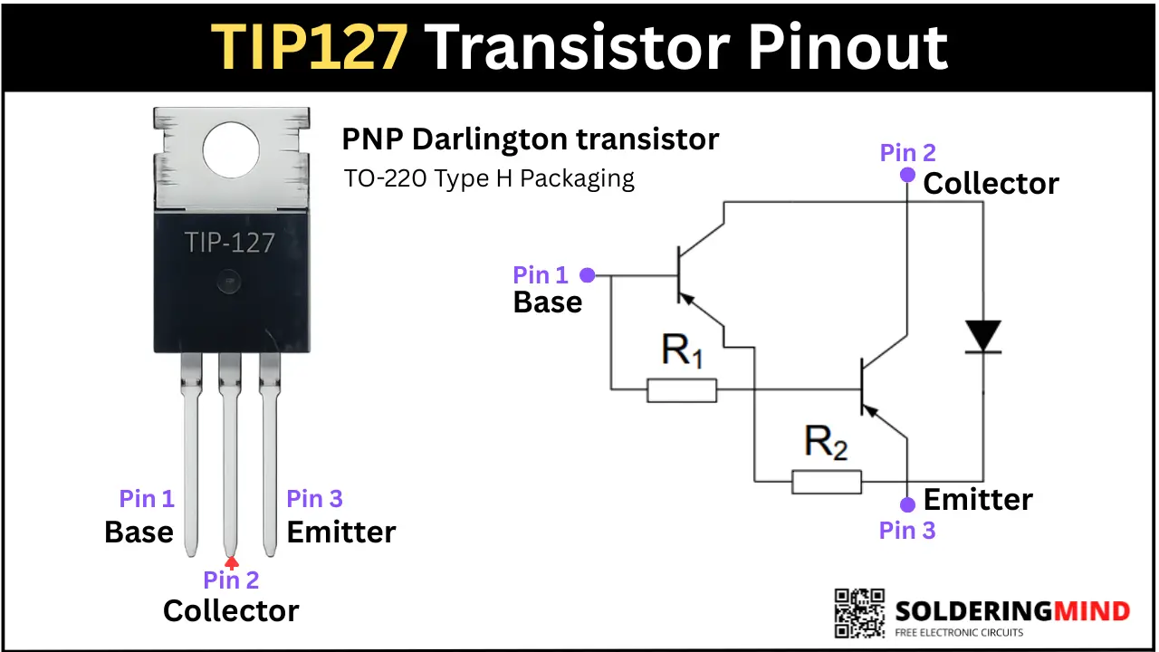
The TIP127 is a 100V, 5A PNP Darlington transistor that comes in TO-220 H type packaging. This transistor provides a high DC gain value of typically 1000 hfe. This high DC gain is achieved by its internal configuration of two PNP transistors. These transistors are commonly used in motor driver circuits, solenoid control circuits, etc.
TIP127 Pinout Diagram
TIP127 Pin Configuration
To check the pinout configuration, you need to hold the transistor so that the number is facing you and three pins are pointing downward. Then count the pins from left to right as Pin 1, 2, and 3. The Pin 1 is Base, Pin 2 is Collector, and Pin 3 is Emitter. The metal part is also internally connected to the collector. Detailed tabulated pin configuration is given below,
| Pin No. | Pin Name |
|---|---|
| 1 | Base (B) |
| 2 | Collector (C) |
| 3 | Emitter (E) |
TIP127 Features and Specifications
- Transistor Type: PNP
- Package Type: TO-220
- Collector-Emitter Voltage is Up to -100V
- Collector-Base voltage is -100 V
- Emitter- Base voltage is -5 V
- Continuous Collector Current is 5A and peak up to 8A
- DC Current Gain is Typically 1000 hfe
- Power Dissipation is 65W
How Does the TIP127 Transistor Work?
The Darlington transistor means two PNP or NPN transistors are used to amplify the input signal. The first transistor’s base pin receiving the input signal and amplifies it, and the second transistor is connected further. This gives a high current gain for the TIP127 transistor. So this transistor can handle a large load of 5A using a small input base voltage.
TIP127 Equivalent and Replacement Transistors
You can use TIP107, BDT62B / BDT62C, BD650, NTE262, MJF127 and TIP137 as the direct replacement transistors. TIP125, TIP126 and MJE2955T can also use as equivalent. Always check the specifications and pinout configuration before replacing with original transistor.
How to Test the TIP127 Transistor Using a Multimeter
Place the multimeter knobs to diode testing mode and performs the testes as per the instructions given in the table below,
| Red Probe On | Black Probe On | Expected Reading | Status |
|---|---|---|---|
| Base (Pin 1) | Emitter (Pin 3) | 1.1V–1.4V | ✅ Good |
| Base (Pin 1) | Collector (Pin 2) | 1.1V–1.4V | ✅ Good |
| Emitter (Pin 3) | Base (Pin 1) | OL (Over Limit) | ✅ Good |
| Collector (Pin 2) | Base (Pin 1) | OL (Over Limit) | ✅ Good |
| Collector (Pin 2) | Emitter (Pin 3) | OL (Both Directions) | ✅ Good |
| Emitter (Pin 3) | Collector (Pin 2) | OL (Both Directions) | ✅ Good |
How to Use the TIP127 in a Circuit
This Darlington transistor is commonly using in high current switching circuits such as motor drivers and LED circuits. Connect the Emitter pin to the positive supply, connect collector to the load like Motors or LED and the other side of the device to ground. Then provide a base voltage through a 1K or 10K resistor to turn On the connected Load.
Common Applications of the TIP127 Transistor
- The transistor is designed for high voltage and high current handling about 100V and 5V so this can used in heavy Motor driver circuits, Relay circuits and DIY audio amplifiers.
- Used in LED lamp dimming circuits.