Your TV remote or MP3 player remote stopped working suddenly? you want to check if it is working or not? The IR remote control tester is used to check if a remote control is working properly or not. The circuit has an IR receiver that detects signals from the remote when any button is pressed on the remote.
IR Remote Control Tester Circuit Diagram
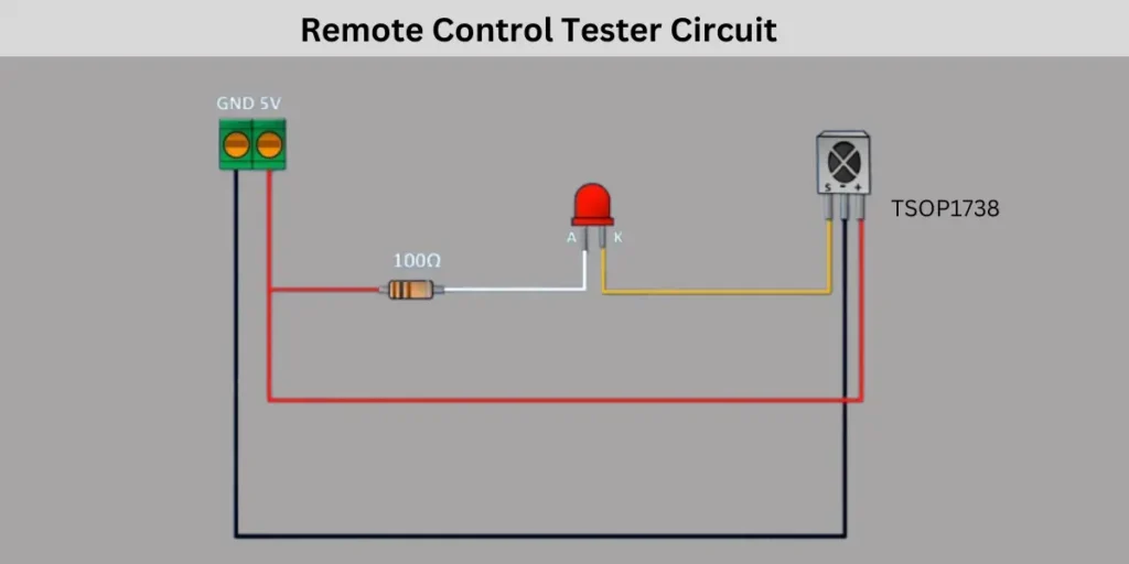
When you press the button on the remote the IR receiver receives the remote signal and the signal is sent to a LED and making it blink. The LED starts to blink only when the remote is sending signals. If the LED is not blinking, it means the remote does not sense the signals and the remote is damaged. A 100Ω resistor is used to protect the LED from too much current. This simple circuit helps to test if the remote control is working without any issues.
Components Required
| Component | Quantity | Description |
|---|---|---|
| IR Receiver Module TSOP1738 | 1 | Detects infrared signals from remote |
| LED (Red) | 1 | Blinks when IR signal is received |
| Resistor (100Ω) | 1 | Limits current to protect the LED |
| Connecting Wires | As needed | Used to connect components |
| Power Supply (5V) | 1 | Provides power to the circuit |
Connection and Working
The circuit connection is very easy and simple. Anyone can configure it on a breadboard. First you need to connect the positive pin of the IR receiver to the 5V power supply and the Ground pin to the negative. The positive and negative supply is taking from the screw terminal which will denoted as 5V supply. You can also use a TSOP1738 or any other IR receiver for this project.
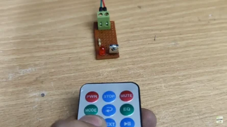
The signal pin of the IR receiver is connected to the cathode pin of the LED. The anode pin of the LED is connected to a 100Ω resistor and the other end of the resistor is connected to the 5V power supply. This resistor is protecting the LED from over current reaching it.
Power the circuit by providing 5V regulated voltage on the circuit and take a TV remote and press the button of the emote. When pressing the remote buttons the IR remote will send a signal to the receiver of our circuit. When the IR receiver gets the signal from the remote it will blink the connected LED. This indicates that the remote control is working properly. There is no problem or issue with the remote.