Let’s build a simple stereo audio amplifier using a KA2206 amplifier IC. This audio amplifier IC delivers 2.3 watts at 4 ohms speakers. If you want to need more power from this amplifier configuration, you can use it on Bridge mode. In bridge mode a maximum of 8.2 watts will be delivered to the speakers.
KA2206 Amplifier Circuit
Components Required to Build Ka2206 Amplifier Circuit
| Component | Value | Quantity |
|---|---|---|
| IC | KA2206 | 1 |
| Resistors | 2.2kΩ | 2 |
| 100Ω | 4 | |
| 10Ω | 2 | |
| Capacitors | 10uF | 2 |
| 100uF | 5 | |
| 470uF | 2 | |
| 1000uF | 1 | |
| 104 (0.1uF) | 2 | |
| Connectors | Audio Input (R, G, L) | 1 set |
| Speaker Output (+SP L+, -SP L-, +SP R+, -SP R-) | 1 set | |
| Power Supply (+VCC, GND) | 1 set |
Circuit connection
The KA2206 amplifier circuit consists of an audio input section, power supply section and speaker output. The audio input section has three terminals labeled R, G, and L, where R is Right channel input and L as left channel input.
The G means Ground connection. Through these input pins we are proving the audio source to amplify. The input signals pass through resistors 2.2kΩ and capacitors of 10uF help in signal conditioning and DC blocking.
The power supply section requires a +VCC connection and a GND terminal to provide operating voltage to the KA2206 IC. It needs a voltage of 3.7v to 12 V DC to work. To stabilize the voltage a 1000uF capacitor is placed across the power lines to reduce noise and fluctuations.
This amplifier circuit output section is suitable to drive two speakers with a watt rating of 3.5w at 4 ohms. The two speakers are connected to the terminals labeled +SP and SP-. These outputs of KA2206 IC is passing through capacitors with values of 100uF and 470uF. The resistors 100Ω and 10Ω ensure smooth audio signal transmission and prevent distortion and oscillations.
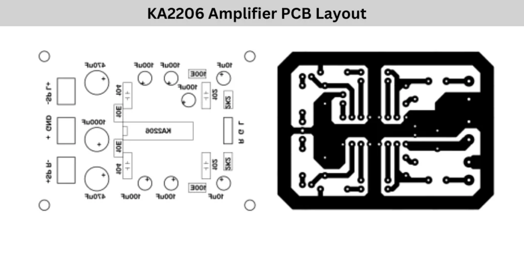
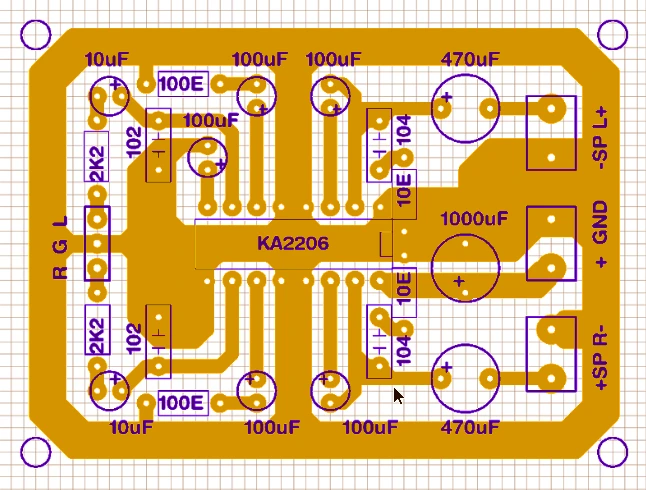
KA2206 Amplifier PCB Layout