The CD6283CS is a high-performance stereo audio amplifier IC designed for applications requiring high-quality sound output with minimal distortion. It delivers 4.6 watts on each channel. These IC-based amplifiers are used in Bluetooth speakers, home audio systems, and car audio systems. The IC provides high-efficiency amplification with excellent sound clarity.
What is the CD6283CS IC?
The CD6283CS is a popular dual-channel audio amplifier IC. This IC needs very minimal number of electronic components required to work. The single vertical flat chip gives around 4.6 watts in 4 ohms speaker.
This can be powered by providing a 12V DC supply to it. If you are given a 9V DC supply, the IC gives 2.5W per channel. So I recommend using a 12V supply to get maximum power output from the audio amplifier IC.
Features of CD6283CS
- The CD6283CS IC provides a High Power Output of
- 2.5W per Channel (Typical) at an input voltage of 9V at 4Ω ohms impedance speaker.
- 4.6W per Channel (Typical) at an input voltage of 12V at 4Ω ohms speaker.
- Very Low Popping Noise while powering the amplifier
- Small Quiescent Current typical Iq = 19mA at Vcc = 9V, Vin = 0
- Soft Clipping Function will prevent distortion at high volume levels.
- it has a Built in Thermal Shutdown Protection to prevent overheating.
- The IC is well designed for 9V and 12V Power Supply
- The Operating Voltage Range is between 6V to 15V DC supply.
Pinout and Pin Configuration
| Pin Number | Pin Name | Description |
|---|---|---|
| 1 | BS1 | Bootstrap 1 |
| 2 | OuT 1 | Audio output 1 |
| 3 | RIPPLE | Ripple filter |
| 4 | NF1 | Negative feedback 1 |
| 5 | IN 1 | Audio input (left) |
| 6 | Pre GND | Pre-ground |
| 7 | IN 2 | Aaudio input 2 (right) |
| 8 | NF2 | Negative feedback 2 |
| 9 | GND | Powering ground connection |
| 10 | OUT 2 | Audio output 2 (RIGHT) |
| 11 | BLS2 | Boostart 2 |
| 12 | VCC | Positive voltage supply |
CD6283CS IC Amplifier Circuit Diagram
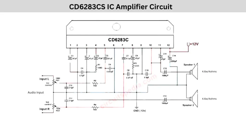
This amplifier schematic represents all detailed connections, including stereo volume control. The volume is adjusted by using a stereo potentiometer rating of 100K. The input left and right channels, the 12V DC supply line, and the stereo output are marked well for better understanding.
Components Required
| Component | Value | Quantity |
|---|---|---|
| CD6283C Audio Amplifier IC | CD6283CS | 1 |
| Resistor R1 | 100 Ω | 1 |
| Resistor R2 | 1 kΩ | 1 |
| Resistor R3 | 100 Ω | 1 |
| Resistor R4 | 1 kΩ | 1 |
| Capacitor C1 | 47 µF | 1 |
| Capacitor C2 | 4.7 µF | 1 |
| Capacitor C3 | 47 µF | 1 |
| Capacitor C4 | 0.1 µF | 1 |
| Capacitor C5 | 0.1 µF | 1 |
| Capacitor C6 | 0.47 nF | 1 |
| Capacitor C7 | 0.1 µF | 1 |
| Capacitor C8 | 0.47 nF | 1 |
| Capacitor C9 | 47 µF | 1 |
| Capacitor C10 | 0.1 µF | 1 |
| Capacitor C11 | 47 µF | 1 |
| Capacitor C12 | 1000 µF | 1 |
| Capacitor C13 | 1000 µF | 1 |
| Capacitor C14 | 2200 µF | 1 |
| Capacitor C15 | 0.1 µF | 1 |
| Capacitor C16 | 1 µF | 1 |
| Capacitor C17 | 1 µF | 1 |
| Stereo Potentiometer | 100 kΩ (Volume Control) | 2 |
| Speakers | 4 Ω, 4.6 W or higher | 2 |
| DC Power Supply | +12 V DC (2–3 A recommended) | 1 |
| Heat Sink | Suitable for CD6283CS | 1 |
| PCB or Perfboard | As required | 1 |
| Terminal Blocks/Wires | As required | Several |
Circuit Connections Explained
The CD6283 IC is powered using a 12V supply voltage. The positive marked in the circuit is goes to the IC pin number 12. The negative terminal of the supply needs to connect ground supply of the battery.
A 2200uf electrolytic capacitor is used in the supply section to filter the DC Supply voltage. It prevents voltage fluctuation and also prevents unwanted noise. You need to attach a good heatsink to protect the IC from overheating.
The left and right channel audio inputs are connected with a 100K potentiometer. This acts like the master volume control for stereo amplifier. The input signal is passed through the coupling capacitor and which will block the DC voltage from entering the audio IC.
It only allows the AC audio signals. Additional resistor and capacitor in the audio input line provide the proper biasing, lower distortion, and filter high frequency audio noises.
In the audio output section, two 4.6 watt 4 ohms speakers are using. If you cannot find a 5 Watt speaker, you can use 6 or 8-watt speakers with 4 ohms impedance. A large coupling capacitors of 1000 μF is placed in both channel output sections to prevent the DC current from reaching the speakers. The ground connection is commonly connected to the main ground connection.
Power Supply Requirements
The power supply needs at least 2A current for better audio quality. I suggest you to use a 12V 3A regulated voltage supply to power the audio amplifier circuit. A well filtered 12V DC adapter or 12V lead acid battery can use this will minimize the humming sound and other unwanted noise to your audio system.
Important Connections Sections In This IC
A 12 DC is connected on the PIN 12 and the ground connection to pin 9. From Pin 11 and Pin 2 Speaker out taken using a 1000uf electrolytic capacitor. The input audio signal is separated using a 100k pot. Which will control the volume of the amplifier.