BC548 is a very common is all electronic circuits and hobby circuits. This general purpose NPN transistor is cheap in price and easy to get from any electronics components shops. In this post I’m sharing the pinout configuration, equivalent number of transistor and its circuit in various working conditions.
What is BC548 Transistor?
The BC548 general purpose small NPN transistor. The transistor is comes in TO-92 packaging. The transistor is deigned for low power applications like switching and signal amplification. It can handle the maximum collector current of upto 100 mA and a collector-emitter voltage of up to 30 V. This transistor is common in LED circuit, relays and low power audio speaker circuits. The BC548 operating by a small current at the base, whuich will control a larger current flow between the collector and emitter. It has a decent current gain of 110 to 800, this is depending on the sub variant as A, B, or C types.
BC548 Transistor Pinout
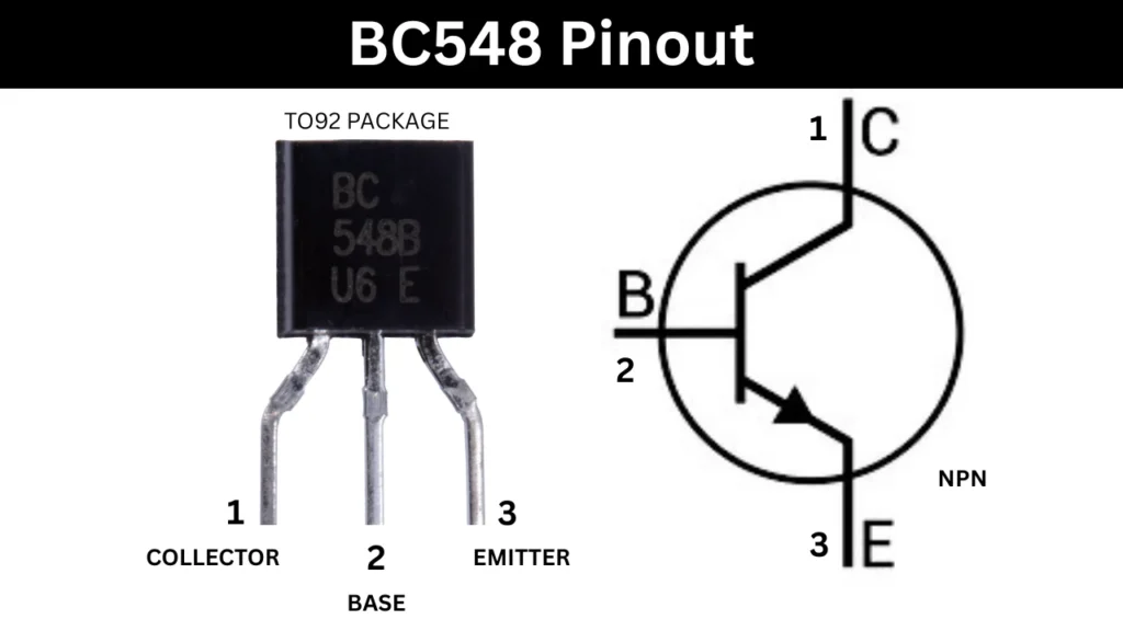
Pinout Configuration
| Pin Number | Name | Description |
|---|---|---|
| 1 | Collector (C) | Current flows out from this pin |
| 2 | Base (B) | Controls the transistor’s operation |
| 3 | Emitter (E) | Current flows into this pin (NPN type) |
Parameters of BC548 A, B, and C Variant
| Parameter | BC548A | BC548B | BC548C |
|---|---|---|---|
| DC Current Gain (hFE) | 110-220 | 200-450 | 420-800 |
| Collector–Emitter Voltage (VCEO) | 30 V | 30 V | 30 V |
| Collector–Base Voltage (VCBO) | 30 V | 30 V | 30 V |
| Emitter–Base Voltage (VEBO) | 6.0 V | 6.0 V | 6.0 V |
| Max Collector Current (IC) | 100 mA | 100 mA | 100 mA |
| Transition Frequency (fT) | 150 MHz | 150 MHz | 150 MHz |
| Package | TO-92 | TO-92 | TO-92 |
Transistor Working
BC548 is a small electronic component that can act like a switch or an amplifier based on its connections and applications. It has three pins of collector, base, and emitter. The transistor works when a small current at the base reached and it will control the larger current flowing between the collector and emitter pins. When the small voltage of 0.6 to 0.7 volts is applied between the base and emitter. Then it will allow a tiny current to flow into the base. This small current then turns on the transistor and allows a much larger current flow from the collector pin to the emitter side. This is how the transistor amplifying the a input weak signal.
If there is no current at the base, the transistor is remains off state, and their is no current flowing through the collector and emitter pins. In this situation the transistor is acts like an open switch. But when the base current is present and strong enough, the transistor is turns on and this time it acting like a closed switch and it allowing the current to pass through the pins. This behavior makes it useful in electronic circuits to control devices like LED circuit, motors controller and signal amplification in audio and radio devices.
Equivalent Transistor
- BC547 – Similar specs, slightly higher voltage rating.
- 2N3904 – Widely used general purpose NPN transistor.
- 2N2222 – Higher current handling than BC548.
- S8050 – Suitable for low-power switching.
- PN2222 – American version of 2N2222 in plastic package.
- KN2222A – Equivalent to 2N2222A, with similar performance.
- C945 (2SC945) – Often used in audio and switching applications.
BC548 Transistor as a Switch Circuit
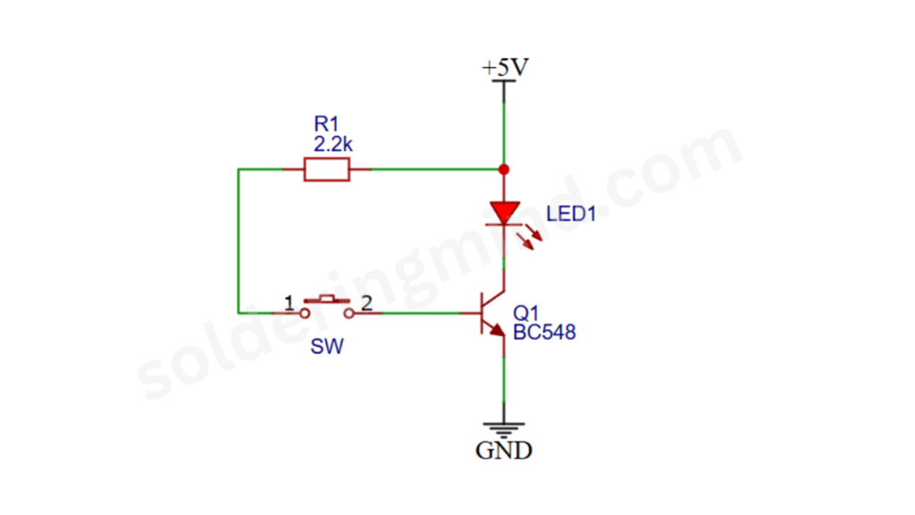
This given circuit in figure 2 shows the use of a BC548 transistor as a switch to controlling the LED light. The circuit is powered by a +5V DC supply. The LED’s cathode pin is connected to the collector of the BC548 transistor and the emitter pin is connected to ground connection.
The base pin is connected to a push button switch through the resistor R1. When the push switch is open, their is no current flowing into the base of the transistor. So the transistor is stays off state and no current will flowing from collector to emitter. As a result, the LED remains in off state.
When the push button switch is pressed a small current will flows from the 5V Dc source through resistor R1 to the base of the BC548. This will turns on the transistor and it will allowing a much larger current to flow from the collector pin to the emitter side. Now this current flows through the LED and the LED will lights up.