In this article i’m sharing a simple DIY Bass treble board using TL074 op-amp IC. You can download the PCB layout and silkscreen to build your own project easily. This circuit works in dual power supply. This TL074 IC based circuit gives a high quality sound output.
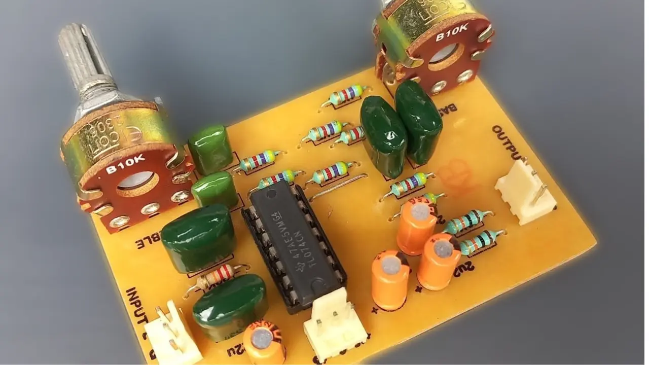
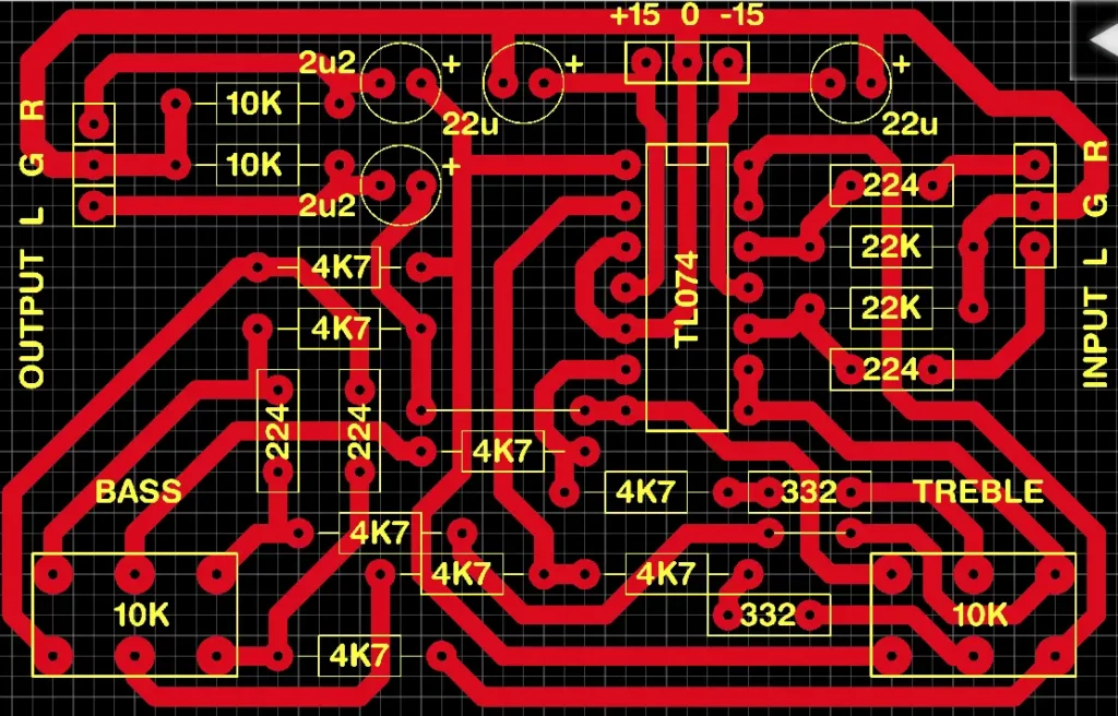
Bass Treble Board PCB Layout
The two 10K dual gangue Liner Pot is used for Bass and Treble controlling. The TL074 is the main IC for controlling the audio bass and treble. Their is no complex design, so you can easily assembled with this guide.
The Tested PCB layout is given below with clear components labeling. The total cost of the project is very less because their is no costly components placed in it. i place IC on a 14 Pin IC socket for easy replacement of IC if Damage occur in future, it will avoids complex disordering process and board track damages.
Components Required
| Sl No | Component | Value | Quantity |
|---|---|---|---|
| 1 | IC | TL074 | 1 |
| 2 | Resistor | 10K | 2 |
| 3 | Resistor | 4.7K (4K7) | 8 |
| 4 | Resistor | 22K | 2 |
| 5 | Capacitor (Electrolytic) | 22µF | 2 |
| 6 | Capacitor (Electrolytic) | 2.2µF | 2 |
| 7 | Capacitor (Ceramic/Film) | 0.22µF (224) | 4 |
| 8 | Capacitor (Ceramic/Film) | 3.3nF (332) | 2 |
| 9 | Potentiometer | 10K (Bass) | 1 |
| 10 | Potentiometer | 10K (Treble) | 1 |
| 11 | Input Connector | L, G, R | 1 set |
| 12 | Output Connector | L, G, R | 1 set |
| 13 | Power Connector | +15V, GND, -15V | 1 set |
Gain of this board is low, if you want more gain add a gain booster board. The noise level of this board is very low, so quiet impressive audio quality you get.
AUDIO LITE JRC4558 Single IC Stereo Bass Treble Board for Amplifier (Active pre Amplifier)
As an Amazon Associate, I earn from qualifying purchases.
🔥 Check Price on Amazon