In this article I’m sharing a simple design of 2 Channel chaser circuit and its PCB layout. This chaser circuit is deigned with a CD4047 IC, The circuit can be directly connect with a 230V Ac supply. This is no additional power needed to work this circuit.
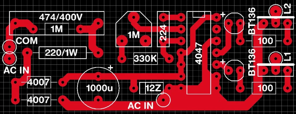
Chaser PCB Layout
Connection Diagram
The connections are very simple and you can connect with the guidance of the given connection diagram. The 230V AC supply is connected to the AC IN labeled points. The phase of AC is connected back to the load and neutral takes from the L1 and L2 for the two lights.
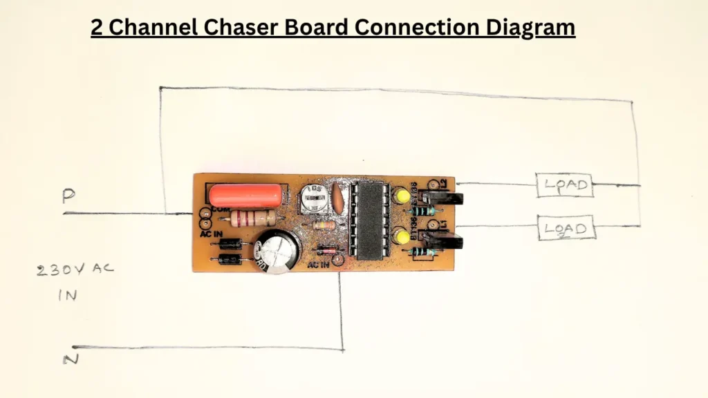
You can use led lights or incandescent lights as the load in this circuit. The AC load is handled by the two BT136 TRIAC. The two LED is also indicating when the sequence is started. This gives a perfect visual appearance and indication of chaser working.
Chaser Board Circuit Diagram
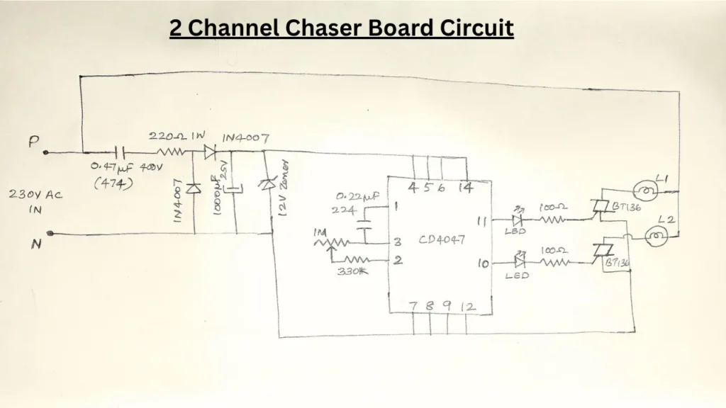
A 1M potentiometer is given in the circuit to control the speed of light ON or OFF. You can adjust this potentiometer based on your requirement. I recommended to adjust the pot only in AC OFF state.
Components Required
| Sl. No | Component Name | Value / Specification | Quantity |
|---|---|---|---|
| 1 | Capacitor (Polyester) | 0.47µF / 400V (474) | 1 |
| 2 | Resistor | 220Ω / 1W | 1 |
| 3 | Diode | 1N4007 | 2 |
| 4 | Electrolytic Capacitor | 1000µF / 25V | 1 |
| 5 | Zener Diode | 12V | 1 |
| 6 | IC | CD4047 | 1 |
| 7 | Capacitor | 0.22µF (224) | 1 |
| 8 | Pot | 1MΩ | 1 |
| 9 | Resistor | 330KΩ | 1 |
| 10 | LED | Standard LED | 2 |
| 11 | Resistor | 100Ω | 2 |
| 12 | TRIAC | BT136 | 2 |
| 13 | Load (Bulb) | 230V AC Bulb (L1, L2) | 2 |
| 14 | Power Supply | 230V AC Input | 1 |
Note: This circuit works on direct AC current, so don’t touch the circuit if the power is in ON state. This may cause electrical shock and dangerous to you. I’m not recommended this circuit for electronics hobbyist or beginners in electronics.