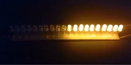
In this article I’m sharing simple 4 channel chaser circuit and its board PCB layout. This circuit is working based on Arduino Nano and you can directly connect the 230V bulb to the circuit but the Arduino needs a separate 5V dc from small SMPS board.
4 Channel Chaser Connection Diagram
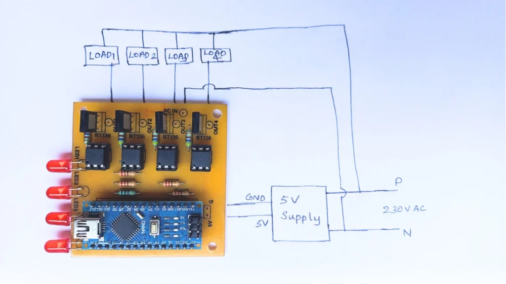
in this connection diagram a 5v supply is connected to the board for Arduino Nano working voltage. You can use a mobile charger old board for getting 5V DC supply. The 230V AC is takes and connected to the load and the neutral connected to the chaser board common neutral point.
Circuit Diagram
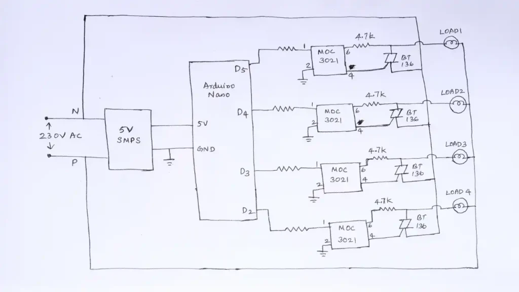
The circuit diagram is simple and easy to understand. This circuit contains few number of electronic components and a single Arduino Nano programmed board. The power supply for the board is gets through the 5V SMPS. The MOC3021 is an optical isolator IC which isolates the small voltage from High AC voltage.
The MOC3021 IC controls the BT136 triac, so the Triac is turns ON or OFF makes the sequence of light ON and OFF. This circuit consist of 4 channel, so you can connect 4 230V AC lights to it. if you want to add more channels make changes in the Arduino programming code.
The project is shared by bijoyts electo thanks to him for such a wonderful electronic project.
Programming Code for Arduino Nano
int led1 = 5;
int led2 = 4;
int led3 = 3;
int led4 = 2;


void setup() {

   pinMode(led1,OUTPUT);
   pinMode(led2,OUTPUT);
   pinMode(led3,OUTPUT);
   pinMode(led4,OUTPUT);

}

void loop()
{
  blink_1();
  blink_1();

 blink_2();
 blink_2();

 blink_3();
 blink_3();

 blink_4();
 blink_4();

 blink_5();
 blink_5();


 blink_6();
 blink_6();


 blink_7();
 blink_7();

blink_8();
blink_8();

 blink_18();

 blink_9();
 blink_9();

 blink_10();
 blink_10();

 blink_11();
 blink_11();

blink_22();
 blink_22();

 blink_12();
 blink_12();

 blink_13();
 blink_13();

  blink_20();
  blink_20();


 blink_14();
  blink_14();

  blink_15();
  blink_15();

  blink_16();
  blink_16();

  blink_17();
  blink_17();

  blink_18();
  blink_18();

   blink_19();
   blink_19();

   blink_20();
   blink_20();

  blink_21();
  blink_21();

  blink_22();
  blink_22();

  blink_23();
  blink_23();

  /////////////////////////////////////////////////////////////////////////////////////////////////////////////////////////


}

/////////////pattern 1///////////////////////////////////////////////////////////////////////////////////////////////////
void blink_1()
{
  int t=150;

  digitalWrite(led1, HIGH );
  delay(t);
  digitalWrite(led2,HIGH);
  delay(t);
  digitalWrite(led3,HIGH);
  delay(t);
   digitalWrite(led4,HIGH);
  delay(t);


  //////////////////////////////////


  digitalWrite(led1, LOW );
  delay(t);
  digitalWrite(led2,LOW);
  delay(t);
  digitalWrite(led3,LOW);
  delay(t);
  digitalWrite(led4,LOW);
  delay(t);


  digitalWrite(led1, HIGH );
  delay(t);
  digitalWrite(led2,HIGH);
  delay(t);
  digitalWrite(led3,HIGH);
  delay(t);
   digitalWrite(led4,HIGH);
  delay(t);


  //////////////////////////////////


  digitalWrite(led1, LOW );
  delay(t);
  digitalWrite(led2,LOW);
  delay(t);
  digitalWrite(led3,LOW);
  delay(t);
  digitalWrite(led4,LOW);
  delay(t);


}

/////////////pattern 2///////////////////////////////////////////////////////////////////////////////////////////////////
void blink_2()
{
  int t=150;

  digitalWrite(led1,HIGH);
  delay(t);
  digitalWrite(led1,LOW);
  digitalWrite(led2,HIGH);
  delay(t);
  digitalWrite(led2,LOW);
  digitalWrite(led3,HIGH);
  delay(t);
  digitalWrite(led3,LOW);
  digitalWrite(led4,HIGH);
  delay(t);
  digitalWrite(led4,LOW);


  digitalWrite(led1, LOW);
  digitalWrite(led2,LOW);
  digitalWrite(led3,LOW);
  digitalWrite(led4,LOW);


///////////////////////////////////////////

  digitalWrite(led1,HIGH);
  delay(t);
  digitalWrite(led1,LOW);
  digitalWrite(led2,HIGH);
  delay(t);
  digitalWrite(led2,LOW);
  digitalWrite(led3,HIGH);
  delay(t);
  digitalWrite(led3,LOW);
  digitalWrite(led4,HIGH);
  delay(t);
  digitalWrite(led4,LOW);


  digitalWrite(led1, LOW);
  digitalWrite(led2,LOW);
  digitalWrite(led3,LOW);
  digitalWrite(led4,LOW);


////////////////////////////////////////

  digitalWrite(led1,HIGH);
  delay(t);
  digitalWrite(led1,LOW);
  digitalWrite(led2,HIGH);
  delay(t);
  digitalWrite(led2,LOW);
  digitalWrite(led3,HIGH);
  delay(t);
  digitalWrite(led3,LOW);
  digitalWrite(led4,HIGH);
  delay(t);
  digitalWrite(led4,LOW);


  digitalWrite(led1, LOW);
  digitalWrite(led2,LOW);
  digitalWrite(led3,LOW);
  digitalWrite(led4,LOW);


}


/////////////pattern 3///////////////////////////////////////////////////////////////////////////////////////////////////
void blink_3()
{
  int t=150;

  digitalWrite(led1,LOW);
  delay(t);
  digitalWrite(led1,HIGH);
  digitalWrite(led2,LOW);
  delay(t);
  digitalWrite(led2,HIGH);
  digitalWrite(led3,LOW);
  delay(t);
  digitalWrite(led3,HIGH);
  digitalWrite(led4,LOW);
  delay(t);
  digitalWrite(led4,HIGH);


  digitalWrite(led1, HIGH);
  digitalWrite(led2,HIGH);
  digitalWrite(led3,HIGH);
  digitalWrite(led4,HIGH);


//////////////////////////////////////

  digitalWrite(led1,LOW);
  delay(t);
  digitalWrite(led1,HIGH);
  digitalWrite(led2,LOW);
  delay(t);
  digitalWrite(led2,HIGH);
  digitalWrite(led3,LOW);
  delay(t);
  digitalWrite(led3,HIGH);
  digitalWrite(led4,LOW);
  delay(t);
  digitalWrite(led4,HIGH);


  digitalWrite(led1, HIGH);
  digitalWrite(led2,HIGH);
  digitalWrite(led3,HIGH);
  digitalWrite(led4,HIGH);


///////////////////////////////////////////

 digitalWrite(led1,LOW);
  delay(t);
  digitalWrite(led1,HIGH);
  digitalWrite(led2,LOW);
  delay(t);
  digitalWrite(led2,HIGH);
  digitalWrite(led3,LOW);
  delay(t);
  digitalWrite(led3,HIGH);
  digitalWrite(led4,LOW);
  delay(t);
  digitalWrite(led4,HIGH);


digitalWrite(led1, HIGH);
digitalWrite(led2,HIGH);
digitalWrite(led3,HIGH);
digitalWrite(led4,HIGH);


}

/////////////pattern 4///////////////////////////////////////////////////////////////////////////////////////////////////KKKKKKKKKKKKKK
void blink_4()
{
  int t=150;

  digitalWrite(led1, HIGH );

  digitalWrite(led3,HIGH);


  digitalWrite(led2,LOW);

  digitalWrite(led4,LOW);


  delay(t);
////////////////
 digitalWrite(led1, LOW );

  digitalWrite(led3,LOW);


  digitalWrite(led2,HIGH);

  digitalWrite(led4,HIGH);


  delay(t);

///////////////////////////////////////////////////////////////////


  digitalWrite(led1, HIGH );

  digitalWrite(led3,HIGH);


  digitalWrite(led2,LOW);

  digitalWrite(led4,LOW);


  delay(t);
////////////////
 digitalWrite(led1, LOW );

  digitalWrite(led3,LOW);


  digitalWrite(led2,HIGH);

  digitalWrite(led4,HIGH);


  delay(t);


  digitalWrite(led1, HIGH );

  digitalWrite(led3,HIGH);


  digitalWrite(led2,LOW);

  digitalWrite(led4,LOW);


  delay(t);
////////////////
 digitalWrite(led1, LOW );

  digitalWrite(led3,LOW);


  digitalWrite(led2,HIGH);

  digitalWrite(led4,HIGH);


  delay(t);

   digitalWrite(led1, HIGH );

  digitalWrite(led3,HIGH);


  digitalWrite(led2,LOW);

  digitalWrite(led4,LOW);


  delay(t);
////////////////
 digitalWrite(led1, LOW );

  digitalWrite(led3,LOW);


  digitalWrite(led2,HIGH);

  digitalWrite(led4,HIGH);


  delay(t);

digitalWrite(led1, HIGH);
digitalWrite(led2,HIGH);
digitalWrite(led3,HIGH);
digitalWrite(led4,HIGH);


  delay(t);


}

////////////////////////////////////////////////////////////////////////////////////////////////////////////////////////////////////////////////////////////////////////
/////////////pattern 5///////////////////////////////////////////////////////////////////////////////////////////////////
void blink_5()
{
  int t=150;

  digitalWrite(led1, HIGH );
  delay(t);
  digitalWrite(led2,HIGH);
  delay(t);
  digitalWrite(led3,HIGH);
  delay(t);
   digitalWrite(led4,HIGH);
  delay(t);


  digitalWrite(led1, LOW );
  delay(t);
  digitalWrite(led2,LOW);
  delay(t);
  digitalWrite(led3,LOW);
  delay(t);
  digitalWrite(led4,LOW);
  delay(t);


  digitalWrite(led4,HIGH);
  delay(t);
  digitalWrite(led3,HIGH);
  delay(t);
  digitalWrite(led2,HIGH);
  delay(t);
  digitalWrite(led1,HIGH);
  delay(t);


  digitalWrite(led4,LOW);
  delay(t);
  digitalWrite(led3,LOW);
  delay(t);
  digitalWrite(led2,LOW);
  delay(t);
  digitalWrite(led1,LOW);
  delay(t);


digitalWrite(led1, LOW);
digitalWrite(led2,LOW);
digitalWrite(led3,LOW);
digitalWrite(led4,LOW);


  digitalWrite(led1, HIGH );
  delay(t);
  digitalWrite(led2,HIGH);
  delay(t);
  digitalWrite(led3,HIGH);
  delay(t);
   digitalWrite(led4,HIGH);
  delay(t);


  digitalWrite(led1, LOW );
  delay(t);
  digitalWrite(led2,LOW);
  delay(t);
  digitalWrite(led3,LOW);
  delay(t);
  digitalWrite(led4,LOW);
  delay(t);

  digitalWrite(led4,HIGH);
  delay(t);
  digitalWrite(led3,HIGH);
  delay(t);
  digitalWrite(led2,HIGH);
  delay(t);
  digitalWrite(led1,HIGH);
  delay(t);


  digitalWrite(led4,LOW);
  delay(t);
  digitalWrite(led3,LOW);
  delay(t);
  digitalWrite(led2,LOW);
  delay(t);
  digitalWrite(led1,LOW);
  delay(t);


digitalWrite(led1, LOW);
digitalWrite(led2,LOW);
digitalWrite(led3,LOW);
digitalWrite(led4,LOW);


}

/////////////pattern 6///////////////////////////////////////////////////////////////////////////////////////////////////
void blink_6()
{
  int t=150;

  digitalWrite(led1, HIGH );
  digitalWrite(led4, HIGH );
  delay(t);
  digitalWrite(led2,HIGH);
  digitalWrite(led3, HIGH );
  delay(t);


  digitalWrite(led1, LOW );
  digitalWrite(led4, LOW );
  delay(t);
  digitalWrite(led2,LOW);
  digitalWrite(led3, LOW );
  delay(t);


  ////////////////


  digitalWrite(led1, HIGH );
  digitalWrite(led4, HIGH );
  delay(t);
  digitalWrite(led2,HIGH);
  digitalWrite(led3, HIGH );
  delay(t);


  digitalWrite(led1, LOW );
  digitalWrite(led4, LOW );
  delay(t);
  digitalWrite(led2,LOW);
  digitalWrite(led3, LOW );
  delay(t);


  //////////////

  digitalWrite(led1, HIGH );
  digitalWrite(led4, HIGH );
  delay(t);
  digitalWrite(led2,HIGH);
  digitalWrite(led3, HIGH );
  delay(t);


  digitalWrite(led1, LOW );
  digitalWrite(led4, LOW );
  delay(t);
  digitalWrite(led2,LOW);
  digitalWrite(led3, LOW );
  delay(t);

}


/////////////pattern 7///////////////////////////////////////////////////////////////////////////////////////////////////
void blink_7()
{
  int t=150;

  digitalWrite(led1, LOW );
  digitalWrite(led4, LOW );
  delay(t);
  digitalWrite(led2,LOW);
  digitalWrite(led3, LOW );
  delay(t);


  digitalWrite(led1, HIGH );
  digitalWrite(led4, HIGH );
  delay(t);
  digitalWrite(led2,HIGH);
  digitalWrite(led3, HIGH );
  delay(t);


  digitalWrite(led1, LOW );
  digitalWrite(led4, LOW );
  delay(t);
  digitalWrite(led2,LOW);
  digitalWrite(led3, LOW );
  delay(t);


  digitalWrite(led1, HIGH );
  digitalWrite(led4, HIGH );
  delay(t);
  digitalWrite(led2,HIGH);
  digitalWrite(led3, HIGH );
  delay(t);


}

////////////////////////////////////////////////////////////////////////////////////////////////////////////////////////////////////////////////////////////////////////
/////////////pattern 8///////////////////////////////////////////////////////////////////////////////////////////////////
void blink_8()
{
  int t=200;


digitalWrite(led1, HIGH);
digitalWrite(led2,HIGH);
digitalWrite(led3,HIGH);
digitalWrite(led4,HIGH);

delay(t);

digitalWrite(led1, LOW);
digitalWrite(led2,LOW);
digitalWrite(led3,LOW);
digitalWrite(led4,LOW);


delay(t);


digitalWrite(led1, HIGH);
digitalWrite(led2,HIGH);
digitalWrite(led3,HIGH);
digitalWrite(led4,HIGH);

delay(t);

digitalWrite(led1, LOW);
digitalWrite(led2,LOW);
digitalWrite(led3,LOW);
digitalWrite(led4,LOW);

delay(t);


digitalWrite(led1, HIGH);
digitalWrite(led2,HIGH);
digitalWrite(led3,HIGH);
digitalWrite(led4,HIGH);

delay(t);

digitalWrite(led1, LOW);
digitalWrite(led2,LOW);
digitalWrite(led3,LOW);
digitalWrite(led4,LOW);


delay(t);


digitalWrite(led1, HIGH);
digitalWrite(led2,HIGH);
digitalWrite(led3,HIGH);
digitalWrite(led4,HIGH);

delay(t);

digitalWrite(led1, LOW);
digitalWrite(led2,LOW);
digitalWrite(led3,LOW);
digitalWrite(led4,LOW);


delay(t);


}


////////////////////////////////////////////////////////////////////////////////////////////////////////////////////////////////////////////////////////////////////////
/////////////pattern 9///////////////////////////////////////////////////////////////////////////////////////////////////
void blink_9()
{
  int t=150;

  digitalWrite(led1, HIGH );
  delay(t);
  digitalWrite(led2,HIGH);
  delay(t);

  digitalWrite(led3,HIGH);
  digitalWrite(led1, LOW );
  delay(t);

  digitalWrite(led4,HIGH);
  digitalWrite(led2, LOW );
  delay(t);


  digitalWrite(led2,HIGH);
  digitalWrite(led4, LOW );
  delay(t);

  digitalWrite(led1,HIGH);
  digitalWrite(led3, LOW );
  delay(t);


  digitalWrite(led2, LOW );
  delay(t);

  digitalWrite(led1, LOW );
  delay(t);


////////////////////////////


  digitalWrite(led1, HIGH );
  delay(t);
  digitalWrite(led2,HIGH);
  delay(t);

  digitalWrite(led3,HIGH);
  digitalWrite(led1, LOW );
  delay(t);

  digitalWrite(led4,HIGH);
  digitalWrite(led2, LOW );
  delay(t);


   digitalWrite(led2,HIGH);
  digitalWrite(led4, LOW );
  delay(t);

   digitalWrite(led1,HIGH);
  digitalWrite(led3, LOW );
  delay(t);


digitalWrite(led2, LOW );
  delay(t);

digitalWrite(led1, LOW );
  delay(t);


//////////////////////////////////////


  digitalWrite(led1, HIGH );
  delay(t);
  digitalWrite(led2,HIGH);
  delay(t);

  digitalWrite(led3,HIGH);
  digitalWrite(led1, LOW );
  delay(t);

  digitalWrite(led4,HIGH);
  digitalWrite(led2, LOW );
  delay(t);


   digitalWrite(led2,HIGH);
  digitalWrite(led4, LOW );
  delay(t);

   digitalWrite(led1,HIGH);
  digitalWrite(led3, LOW );
  delay(t);


digitalWrite(led2, LOW );
  delay(t);

digitalWrite(led1, LOW );
  delay(t);


}


////////////////////////////////////////////////////////////////////////////////////////////////////////////////////////////////////////////////////////////////////////
/////////////pattern 10///////////////////////////////////////////////////////////////////////////////////////////////////
void blink_10()
{
  int t=150;

  digitalWrite(led1, LOW );
  digitalWrite(led2, LOW );
  digitalWrite(led3, LOW );
  digitalWrite(led4, LOW );
  delay(t);
   digitalWrite(led1, HIGH );
  delay(t);
   digitalWrite(led1, LOW );
  delay(t);
  digitalWrite(led1, HIGH );
  delay(t);
   digitalWrite(led1, LOW );
  delay(t);
   digitalWrite(led2, HIGH );
  delay(t);
  digitalWrite(led2, LOW );
  delay(t);
   digitalWrite(led2, HIGH );
  delay(t);
    digitalWrite(led2, LOW );
  delay(t);
   digitalWrite(led3, HIGH );
  delay(t);
  digitalWrite(led3, LOW );
  delay(t);
   digitalWrite(led3, HIGH );
  delay(t);
   digitalWrite(led3, LOW );
  delay(t);
   digitalWrite(led4, HIGH );
  delay(t);
  digitalWrite(led4, LOW );
  delay(t);
   digitalWrite(led4, HIGH );
  delay(t);
    digitalWrite(led4, LOW );
  delay(t);

    digitalWrite(led3, HIGH );
  delay(t);
   digitalWrite(led3, LOW );
  delay(t);
  digitalWrite(led3, HIGH );
  delay(t);
   digitalWrite(led3, LOW );
  delay(t);
   digitalWrite(led2, HIGH );
  delay(t);
  digitalWrite(led2, LOW );
  delay(t);
   digitalWrite(led2, HIGH );
  delay(t);
    digitalWrite(led2, LOW );
  delay(t);
   digitalWrite(led1, HIGH );
  delay(t);
  digitalWrite(led1, LOW );
  delay(t);
   digitalWrite(led1, HIGH );
  delay(t);
   digitalWrite(led1, LOW );
  delay(t);
   digitalWrite(led2, HIGH );
  delay(t);
  digitalWrite(led2, LOW );
  delay(t);
   digitalWrite(led2, HIGH );
  delay(t);
    digitalWrite(led2, LOW );
  delay(t);
    digitalWrite(led3, HIGH );
  delay(t);
   digitalWrite(led3, LOW );
  delay(t);
  digitalWrite(led3, HIGH );
  delay(t);
   digitalWrite(led3, LOW );
  delay(t);
   digitalWrite(led4, HIGH );
  delay(t);
  digitalWrite(led4, LOW );
  delay(t);
   digitalWrite(led4, HIGH );
  delay(t);
    digitalWrite(led4, LOW );
  delay(t);
   digitalWrite(led3, HIGH );
  delay(t);
  digitalWrite(led3, LOW );
  delay(t);
   digitalWrite(led3, HIGH );
  delay(t);
   digitalWrite(led3, LOW );
  delay(t);

   digitalWrite(led2, HIGH );
  delay(t);
  digitalWrite(led2, LOW );
  delay(t);
   digitalWrite(led2, HIGH );
  delay(t);
    digitalWrite(led2, LOW );
  delay(t);
   digitalWrite(led1, HIGH );
  delay(t);
  digitalWrite(led1, LOW );
  delay(t);
   digitalWrite(led1, HIGH );
  delay(t);
   digitalWrite(led1, LOW );
  delay(t);

}
////////////////////////////////////////////////////////////////////////////////////////////////////////////////////////////////////////////////////////////////////////
/////////////pattern 11///////////////////////////////////////////////////////////////////////////////////////////////////
void blink_11()
{
  int t=150;

  digitalWrite(led1, HIGH );
  delay(t);
  digitalWrite(led2,HIGH);
  delay(t);
  digitalWrite(led3,HIGH);
  delay(t);
   digitalWrite(led4,HIGH);
  delay(t);


  //////////////////////////////////


   digitalWrite(led4,LOW);
  delay(t);
  digitalWrite(led3,LOW);
  delay(t);
  digitalWrite(led2,LOW);
  delay(t);
    digitalWrite(led1, LOW );
  delay(t);


  digitalWrite(led1, HIGH );
  delay(t);
  digitalWrite(led2,HIGH);
  delay(t);
  digitalWrite(led3,HIGH);
  delay(t);
   digitalWrite(led4,HIGH);
  delay(t);


  //////////////////////////////////


   digitalWrite(led4,LOW);
  delay(t);
  digitalWrite(led3,LOW);
  delay(t);
  digitalWrite(led2,LOW);
  delay(t);
    digitalWrite(led1, LOW );
  delay(t);

}


////////////////////////////////////////////////////////////////////////////////////////////////////////////////////////////////////////////////////////////////////////
/////////////pattern 12///////////////////////////////////////////////////////////////////////////////////////////////////
void blink_12()
{
  int t=180;

  digitalWrite(led1, HIGH );
  digitalWrite(led2, HIGH );
  delay(t);
  digitalWrite(led1, LOW );
  digitalWrite(led2, LOW );
  digitalWrite(led3, HIGH );
  digitalWrite(led4, HIGH );
  delay(t);
  digitalWrite(led3, LOW );
  digitalWrite(led4, LOW );
  digitalWrite(led1, HIGH );
  digitalWrite(led2, HIGH );
  delay(t);
  digitalWrite(led1, LOW );
  digitalWrite(led2, LOW );
  digitalWrite(led3, HIGH );
  digitalWrite(led4, HIGH );
  delay(t);
  digitalWrite(led3, LOW );
  digitalWrite(led4, LOW );
  digitalWrite(led1, HIGH );
  digitalWrite(led2, HIGH );
  delay(t);
   digitalWrite(led1, LOW );
  digitalWrite(led2, LOW );
  digitalWrite(led3, HIGH );
  digitalWrite(led4, HIGH );
  delay(t);
  digitalWrite(led3, LOW );
  digitalWrite(led4, LOW );
  digitalWrite(led1, HIGH );
  digitalWrite(led2, HIGH );
  delay(t);
  digitalWrite(led1, LOW );
  digitalWrite(led2, LOW );
  digitalWrite(led3, HIGH );
  digitalWrite(led4, HIGH );
  delay(t);
  digitalWrite(led3, LOW );
  digitalWrite(led4, LOW );
  digitalWrite(led1, HIGH );
  digitalWrite(led2, HIGH );
  delay(t);
}


////////////////////////////////////////////////////////////////////////////////////////////////////////////////////////////////////////////////////////////////////////
/////////////pattern 13///////////////////////////////////////////////////////////////////////////////////////////////////
void blink_13()
{
  int t=150;
  digitalWrite(led1, HIGH );
  delay(t);
  digitalWrite(led2, HIGH );
  delay(t);
  digitalWrite(led3, HIGH );
  delay(t);
  digitalWrite(led1, LOW );
  delay(t);
  digitalWrite(led4, HIGH );
  delay(t);
  digitalWrite(led2, LOW );
  delay(t);
  digitalWrite(led3, LOW );
  delay(t);
  digitalWrite(led4, LOW );
  delay(t);

  digitalWrite(led1, HIGH );
  delay(t);
  digitalWrite(led2, HIGH );
  delay(t);
  digitalWrite(led3, HIGH );
  delay(t);
  digitalWrite(led1, LOW );
  delay(t);
  digitalWrite(led4, HIGH );
  delay(t);
  digitalWrite(led2, LOW );
  delay(t);
  digitalWrite(led3, LOW );
  delay(t);
  digitalWrite(led4, LOW );
  delay(t);
}

////////////////////////////////////////////////////////////////////////////////////////////////////////////////////////////////////////////////////////////////////////
/////////////pattern 14///////////////////////////////////////////////////////////////////////////////////////////////////
void blink_14()
{
  int t=150;

  digitalWrite(led1, HIGH );
  delay(t);
  digitalWrite(led1, LOW );
  delay(t);
  digitalWrite(led2, HIGH );
  delay(t);
  digitalWrite(led2, LOW );
  delay(t);
  digitalWrite(led3, HIGH );
  delay(t);
  digitalWrite(led3, LOW );
  delay(t);
  digitalWrite(led4, HIGH );
  delay(t);
   digitalWrite(led4, LOW );
  delay(t);
  digitalWrite(led1, HIGH );
  delay(t);
  digitalWrite(led1, LOW );
  delay(t);
  digitalWrite(led2, HIGH );
  delay(t);
  digitalWrite(led2, LOW );
  delay(t);
  digitalWrite(led3, HIGH );
  delay(t);
  digitalWrite(led3, LOW );
  delay(t);
   digitalWrite(led4, HIGH );
  delay(t);
    digitalWrite(led4, LOW );
  delay(t);
    digitalWrite(led4, HIGH );
  delay(t);
  digitalWrite(led1, HIGH );
  delay(t);
  digitalWrite(led1, LOW );
  delay(t);
  digitalWrite(led2, HIGH );
  delay(t);
   digitalWrite(led2, LOW );
  delay(t);
  digitalWrite(led3, HIGH );
  delay(t);
  digitalWrite(led3, LOW );
  delay(t);
   digitalWrite(led3, HIGH );
  delay(t);
  digitalWrite(led1, HIGH );
  delay(t);
  digitalWrite(led1, LOW );
  delay(t);
  digitalWrite(led2, HIGH );
  delay(t);
     digitalWrite(led2, LOW );
  delay(t);
    digitalWrite(led2, HIGH );
  delay(t);
  digitalWrite(led1, HIGH );
  delay(t);
    digitalWrite(led1, LOW );
  delay(t);
    digitalWrite(led1, HIGH );
  delay(t);
   delay(t);


  digitalWrite(led1, LOW );
  digitalWrite(led2, LOW );
  digitalWrite(led3, LOW );
  digitalWrite(led4, LOW );
 delay(t);
 delay(t);


}


  ////////////////////////////////////////////////////////////////////////////////////////////////////////////////////////////////////////////////////////////////////////
/////////////pattern 15///////////////////////////////////////////////////////////////////////////////////////////////////
void blink_15()
{
  int t=200;

  digitalWrite(led1, HIGH );
  digitalWrite(led2, HIGH );
  digitalWrite(led3, HIGH );
  digitalWrite(led4, HIGH );
  delay(t);
  digitalWrite(led4, LOW );
  delay(t);
  digitalWrite(led4, HIGH );
  delay(t);
  digitalWrite(led3, LOW );
  delay(t);
  digitalWrite(led3, HIGH );
  delay(t);
  digitalWrite(led2, LOW );
  delay(t);
  digitalWrite(led2, HIGH );
  delay(t);
  digitalWrite(led1, LOW );
  delay(t);
  digitalWrite(led1, HIGH );
  delay(t);

  digitalWrite(led1, HIGH );
  digitalWrite(led2, HIGH );
  digitalWrite(led3, HIGH );
  digitalWrite(led4, HIGH );
  delay(t);
  digitalWrite(led4, LOW );
  delay(t);
  digitalWrite(led4, HIGH );
  delay(t);
  digitalWrite(led3, LOW );
  delay(t);
  digitalWrite(led3, HIGH );
  delay(t);
  digitalWrite(led2, LOW );
  delay(t);
  digitalWrite(led2, HIGH );
  delay(t);
  digitalWrite(led1, LOW );
  delay(t);
  digitalWrite(led1, HIGH );
  delay(t);

}

  ////////////////////////////////////////////////////////////////////////////////////////////////////////////////////////////////////////////////////////////////////////
/////////////pattern 16///////////////////////////////////////////////////////////////////////////////////////////////////
void blink_16()
{
  int t=150;
  digitalWrite(led3, LOW );
  digitalWrite(led4, LOW );
  digitalWrite(led1, HIGH );
  digitalWrite(led2, HIGH );
  delay(t);
  digitalWrite(led1, LOW );
  digitalWrite(led2, LOW );
  delay(t);
   digitalWrite(led1, HIGH );
  digitalWrite(led2, HIGH );
  delay(t);
  digitalWrite(led1, LOW );
  digitalWrite(led2, LOW );
  delay(t);
   digitalWrite(led1, HIGH );
  digitalWrite(led2, HIGH );
  delay(t);
  digitalWrite(led1, LOW );
  digitalWrite(led2, LOW );
  delay(t);


  digitalWrite(led3, HIGH );
  digitalWrite(led4, HIGH );
  delay(t);
  digitalWrite(led3, LOW );
  digitalWrite(led4, LOW );
  delay(t);
   digitalWrite(led3, HIGH );
  digitalWrite(led4, HIGH );
  delay(t);
  digitalWrite(led3, LOW );
  digitalWrite(led4, LOW );
  delay(t);
  digitalWrite(led3, HIGH );
  digitalWrite(led4, HIGH );
  delay(t);
  digitalWrite(led3, LOW );
  digitalWrite(led4, LOW );
  delay(t);
}


   ////////////////////////////////////////////////////////////////////////////////////////////////////////////////////////////////////////////////////////////////////////
/////////////pattern 17///////////////////////////////////////////////////////////////////////////////////////////////////
void blink_17()
{
  int t=150;
  digitalWrite(led1, HIGH );
  digitalWrite(led2, HIGH );
  digitalWrite(led3, HIGH );
  digitalWrite(led4, HIGH );
  delay(t);
  digitalWrite(led1, LOW );
  digitalWrite(led2, LOW );
  delay(t);
  digitalWrite(led1, HIGH );
  digitalWrite(led3, LOW );
  delay(t);
  digitalWrite(led2, HIGH );
  digitalWrite(led4, LOW );
  delay(t);
  digitalWrite(led4, HIGH );
  digitalWrite(led2, LOW );
   delay(t);
  digitalWrite(led3, HIGH );
  digitalWrite(led1, LOW );

  delay(t);
  digitalWrite(led1, HIGH );
  digitalWrite(led3, LOW );
  delay(t);
  digitalWrite(led2, HIGH );
  digitalWrite(led4, LOW );
  delay(t);
  digitalWrite(led4, HIGH );
  digitalWrite(led2, LOW );
   delay(t);
  digitalWrite(led3, HIGH );
  digitalWrite(led1, LOW );

}

   ////////////////////////////////////////////////////////////////////////////////////////////////////////////////////////////////////////////////////////////////////////
/////////////pattern 18///////////////////////////////////////////////////////////////////////////////////////////////////
void blink_18()
{
  int t=150;
  digitalWrite(led1, LOW );
  digitalWrite(led2, LOW );
  digitalWrite(led3, LOW );
  digitalWrite(led4, LOW );

  digitalWrite(led1, HIGH );
   delay(t);
  digitalWrite(led1, LOW );
  digitalWrite(led2, HIGH );
  delay(t);
  digitalWrite(led3, HIGH );
  digitalWrite(led2, LOW );
  delay(t);
  digitalWrite(led4, HIGH );
  digitalWrite(led3, LOW );
  delay(t);
  digitalWrite(led4, LOW );
  digitalWrite(led1, HIGH );
   delay(t);
  digitalWrite(led1, LOW );
  digitalWrite(led2, HIGH );
  delay(t);
  digitalWrite(led3, HIGH );
  digitalWrite(led2, LOW );
  delay(t);
  digitalWrite(led4, HIGH );
  digitalWrite(led3, LOW );
  delay(t);
  digitalWrite(led4, LOW );
 digitalWrite(led1, HIGH );
   delay(t);
  digitalWrite(led1, LOW );
  digitalWrite(led2, HIGH );
  delay(t);
  digitalWrite(led3, HIGH );
  digitalWrite(led2, LOW );
  delay(t);
  digitalWrite(led4, HIGH );
  digitalWrite(led3, LOW );
  delay(t);
  digitalWrite(led4, LOW );
  digitalWrite(led1, HIGH );
   delay(t);
  digitalWrite(led1, LOW );
  digitalWrite(led2, HIGH );
  delay(t);
  digitalWrite(led3, HIGH );
  digitalWrite(led2, LOW );
  delay(t);
  digitalWrite(led4, HIGH );
  digitalWrite(led3, LOW );
  delay(t);


  digitalWrite(led4, LOW );
  digitalWrite(led3, HIGH );
  delay(t);
  digitalWrite(led2, HIGH );
  digitalWrite(led3, LOW );
  delay(t);
  digitalWrite(led1, HIGH );
  digitalWrite(led2, LOW );
  delay(t);
  digitalWrite(led1, LOW );
  digitalWrite(led3, LOW );
  digitalWrite(led4, HIGH );
  delay(t);
  digitalWrite(led3, HIGH );
  digitalWrite(led4, LOW );
  delay(t);
  digitalWrite(led2, HIGH );
  digitalWrite(led3, LOW );
  delay(t);
  digitalWrite(led1, HIGH );
  digitalWrite(led2, LOW );
  delay(t);

  digitalWrite(led1, LOW );
  digitalWrite(led3, LOW );
  digitalWrite(led4, HIGH );
  delay(t);
  digitalWrite(led3, HIGH );
  digitalWrite(led4, LOW );
  delay(t);
  digitalWrite(led2, HIGH );
  digitalWrite(led3, LOW );
  delay(t);
  digitalWrite(led1, HIGH );
  digitalWrite(led2, LOW );
  delay(t);
 digitalWrite(led1, LOW );
  digitalWrite(led3, LOW );
  digitalWrite(led4, HIGH );
  delay(t);
  digitalWrite(led3, HIGH );
  digitalWrite(led4, LOW );
  delay(t);
  digitalWrite(led2, HIGH );
  digitalWrite(led3, LOW );
  delay(t);
  digitalWrite(led1, HIGH );
  digitalWrite(led2, LOW );
  delay(t);

  //////////////////////////////////////////////////////////////////

   digitalWrite(led1, HIGH );
   delay(t);
  digitalWrite(led1, LOW );
  digitalWrite(led2, HIGH );
  delay(t);
  digitalWrite(led3, HIGH );
  digitalWrite(led2, LOW );
  delay(t);
  digitalWrite(led4, HIGH );
  digitalWrite(led3, LOW );
  delay(t);


  digitalWrite(led4, LOW );
  digitalWrite(led3, HIGH );
  delay(t);
  digitalWrite(led2, HIGH );
  digitalWrite(led3, LOW );
  delay(t);
  digitalWrite(led1, HIGH );
  digitalWrite(led2, LOW );
  delay(t);

   digitalWrite(led1, LOW );
  digitalWrite(led2, HIGH );
  delay(t);
  digitalWrite(led3, HIGH );
  digitalWrite(led2, LOW );
  delay(t);
  digitalWrite(led4, HIGH );
  digitalWrite(led3, LOW );
  delay(t);

  digitalWrite(led4, LOW );
  digitalWrite(led3, HIGH );
  delay(t);
  digitalWrite(led2, HIGH );
  digitalWrite(led3, LOW );
  delay(t);
  digitalWrite(led1, HIGH );
  digitalWrite(led2, LOW );
  delay(t);

  digitalWrite(led1, LOW );
  digitalWrite(led2, HIGH );
  delay(t);
  digitalWrite(led3, HIGH );
  digitalWrite(led2, LOW );
  delay(t);
  digitalWrite(led4, HIGH );
  digitalWrite(led3, LOW );
  delay(t);

  digitalWrite(led4, LOW );
  digitalWrite(led3, HIGH );
  delay(t);
  digitalWrite(led2, HIGH );
  digitalWrite(led3, LOW );
  delay(t);
  digitalWrite(led1, HIGH );
  digitalWrite(led2, LOW );
  delay(t);

    digitalWrite(led1, LOW );
  digitalWrite(led2, HIGH );
  delay(t);
  digitalWrite(led3, HIGH );
  digitalWrite(led2, LOW );
  delay(t);
  digitalWrite(led4, HIGH );
  digitalWrite(led3, LOW );
  delay(t);

  digitalWrite(led4, LOW );
  digitalWrite(led3, HIGH );
  delay(t);
  digitalWrite(led2, HIGH );
  digitalWrite(led3, LOW );
  delay(t);
  digitalWrite(led1, HIGH );
  digitalWrite(led2, LOW );
  delay(t);

}

    ////////////////////////////////////////////////////////////////////////////////////////////////////////////////////////////////////////////////////////////////////////
/////////////pattern 19///////////////////////////////////////////////////////////////////////////////////////////////////
void blink_19()
{
  int t=150;
  digitalWrite(led1, LOW );
  digitalWrite(led2, LOW );
  digitalWrite(led3, LOW );
  digitalWrite(led4, LOW );

  digitalWrite(led1, HIGH );
   delay(t);
  digitalWrite(led1, LOW );
  digitalWrite(led2, HIGH );
  delay(t);
  digitalWrite(led3, HIGH );
  digitalWrite(led2, LOW );
  delay(t);
  digitalWrite(led4, HIGH );
  digitalWrite(led3, LOW );
  delay(t);
  digitalWrite(led4, LOW );
  digitalWrite(led1, HIGH );
   delay(t);
  digitalWrite(led1, LOW );
  digitalWrite(led2, HIGH );
  delay(t);
  digitalWrite(led3, HIGH );
  digitalWrite(led2, LOW );
  delay(t);
  digitalWrite(led4, HIGH );
  digitalWrite(led3, LOW );
  delay(t);
  digitalWrite(led4, LOW );
 digitalWrite(led1, HIGH );
   delay(t);
  digitalWrite(led1, LOW );
  digitalWrite(led2, HIGH );
  delay(t);
  digitalWrite(led3, HIGH );
  digitalWrite(led2, LOW );
  delay(t);
  digitalWrite(led4, HIGH );
  digitalWrite(led3, LOW );
  delay(t);
  digitalWrite(led4, LOW );
  digitalWrite(led1, HIGH );
   delay(t);
  digitalWrite(led1, LOW );
  digitalWrite(led2, HIGH );
  delay(t);
  digitalWrite(led3, HIGH );
  digitalWrite(led2, LOW );
  delay(t);
  digitalWrite(led4, HIGH );
  digitalWrite(led3, LOW );
  delay(t);
  digitalWrite(led4, LOW );
  digitalWrite(led1, HIGH );
  delay(t);
  digitalWrite(led2, HIGH );
  delay(t);
  digitalWrite(led3, HIGH );
   delay(t);
  digitalWrite(led4, HIGH );
  delay(t);
  delay(t);
  delay(t);
  delay(t);
  digitalWrite(led1, LOW );
  digitalWrite(led2, LOW );
  digitalWrite(led3, LOW );
  digitalWrite(led4, LOW );
  delay(t);
  delay(t);

   digitalWrite(led4, HIGH );
  delay(t);
  digitalWrite(led3, HIGH );
  digitalWrite(led4, LOW );
  delay(t);
  digitalWrite(led2, HIGH );
  digitalWrite(led3, LOW );
  delay(t);
  digitalWrite(led1, HIGH );
  digitalWrite(led2, LOW );
  delay(t);

  digitalWrite(led1, LOW );
  digitalWrite(led3, LOW );
  digitalWrite(led4, HIGH );
  delay(t);
  digitalWrite(led3, HIGH );
  digitalWrite(led4, LOW );
  delay(t);
  digitalWrite(led2, HIGH );
  digitalWrite(led3, LOW );
  delay(t);
  digitalWrite(led1, HIGH );
  digitalWrite(led2, LOW );
  delay(t);
 digitalWrite(led1, LOW );
  digitalWrite(led3, LOW );
  digitalWrite(led4, HIGH );
  delay(t);
  digitalWrite(led3, HIGH );
  digitalWrite(led4, LOW );
  delay(t);
  digitalWrite(led2, HIGH );
  digitalWrite(led3, LOW );
  delay(t);
  digitalWrite(led1, HIGH );
  digitalWrite(led2, LOW );
  delay(t);
  digitalWrite(led1, LOW );
  delay(t);
  digitalWrite(led4, HIGH );
  delay(t);
  digitalWrite(led3, HIGH );
  digitalWrite(led4, LOW );
  delay(t);
  digitalWrite(led2, HIGH );
  digitalWrite(led3, LOW );
  delay(t);
  digitalWrite(led1, HIGH );
  digitalWrite(led2, LOW );
  delay(t);
  digitalWrite(led1, LOW );
  delay(t);


  digitalWrite(led4, HIGH );
  delay(t);
  digitalWrite(led3, HIGH );
  delay(t);
  digitalWrite(led2, HIGH );
   delay(t);
  digitalWrite(led1, HIGH );
  delay(t);
  delay(t);
  delay(t);
  delay(t);
  delay(t);
  delay(t);
  delay(t);

  digitalWrite(led1, LOW );
  digitalWrite(led2, LOW );
  digitalWrite(led3, LOW );
  digitalWrite(led4, LOW );
  delay(t);
  delay(t);
}

     ////////////////////////////////////////////////////////////////////////////////////////////////////////////////////////////////////////////////////////////////////////
/////////////pattern 20///////////////////////////////////////////////////////////////////////////////////////////////////
void blink_20()
{
  int t=150;
  digitalWrite(led1, LOW );
  digitalWrite(led2, LOW );
  digitalWrite(led3, LOW );
  digitalWrite(led4, LOW );

  digitalWrite(led1, HIGH );
   delay(t);
  digitalWrite(led1, LOW );
  digitalWrite(led2, HIGH );
  delay(t);
  digitalWrite(led3, HIGH );
  digitalWrite(led2, LOW );
  delay(t);
  digitalWrite(led4, HIGH );
  digitalWrite(led3, LOW );
  delay(t);
  digitalWrite(led4, LOW );

  digitalWrite(led1, HIGH );
   delay(t);
  digitalWrite(led1, LOW );
  digitalWrite(led2, HIGH );
  delay(t);
  digitalWrite(led3, HIGH );
  digitalWrite(led2, LOW );
  delay(t);
  digitalWrite(led4, HIGH );
  digitalWrite(led3, LOW );
  delay(t);
 // digitalWrite(led4, LOW );

  digitalWrite(led1, HIGH );
  digitalWrite(led2, HIGH );
  digitalWrite(led3, HIGH );
  digitalWrite(led4, HIGH );
  delay(t);
  delay(t);

}

     ////////////////////////////////////////////////////////////////////////////////////////////////////////////////////////////////////////////////////////////////////////
/////////////pattern 21///////////////////////////////////////////////////////////////////////////////////////////////////
void blink_21()
{
  int t=150;
  digitalWrite(led1, LOW );
  digitalWrite(led2, LOW );
  digitalWrite(led3, LOW );
  digitalWrite(led4, LOW );
    digitalWrite(led4, HIGH );
  delay(t);
  digitalWrite(led3, HIGH );
  digitalWrite(led4, LOW );
  delay(t);
  digitalWrite(led2, HIGH );
  digitalWrite(led3, LOW );
  delay(t);
  digitalWrite(led1, HIGH );
  digitalWrite(led2, LOW );
  delay(t);

  digitalWrite(led1, LOW );
  digitalWrite(led3, LOW );
  digitalWrite(led4, HIGH );
  delay(t);
  digitalWrite(led3, HIGH );
  digitalWrite(led4, LOW );
  delay(t);
  digitalWrite(led2, HIGH );
  digitalWrite(led3, LOW );
  delay(t);
  digitalWrite(led1, HIGH );
  digitalWrite(led2, LOW );
  delay(t);
  digitalWrite(led1, HIGH );
  digitalWrite(led2, HIGH );
  digitalWrite(led3, HIGH );
  digitalWrite(led4, HIGH );
  delay(t);
  delay(t);
}

     ////////////////////////////////////////////////////////////////////////////////////////////////////////////////////////////////////////////////////////////////////////
/////////////pattern 22///////////////////////////////////////////////////////////////////////////////////////////////////
void blink_22()
{
  int t=150;
  digitalWrite(led1, LOW );
  digitalWrite(led2, LOW );
  digitalWrite(led3, LOW );
  digitalWrite(led4, LOW );

    digitalWrite(led1, HIGH );
   delay(t);
  digitalWrite(led1, LOW );
  digitalWrite(led2, HIGH );
  delay(t);
  digitalWrite(led3, HIGH );
  digitalWrite(led2, LOW );
  delay(t);
  digitalWrite(led4, HIGH );
  digitalWrite(led3, LOW );
  delay(t);
  //digitalWrite(led4, LOW );
  //delay(t);
  digitalWrite(led1, HIGH );
  digitalWrite(led2, HIGH );
  digitalWrite(led3, HIGH );
  digitalWrite(led4, HIGH );
  delay(t);
  delay(t);

 digitalWrite(led1, LOW );
  digitalWrite(led3, LOW );
  digitalWrite(led4, HIGH );
  delay(t);
  digitalWrite(led3, HIGH );
  digitalWrite(led4, LOW );
  delay(t);
  digitalWrite(led2, HIGH );
  digitalWrite(led3, LOW );
  delay(t);
  digitalWrite(led1, HIGH );
  digitalWrite(led2, LOW );
  delay(t);
  // digitalWrite(led1, LOW );
   //delay(t);
  digitalWrite(led1, HIGH );
  digitalWrite(led2, HIGH );
  digitalWrite(led3, HIGH );
  digitalWrite(led4, HIGH );
  delay(t);
  delay(t);

}


     ////////////////////////////////////////////////////////////////////////////////////////////////////////////////////////////////////////////////////////////////////////
/////////////pattern 23///////////////////////////////////////////////////////////////////////////////////////////////////
void blink_23()
{
  int t=150;


  digitalWrite(led1, HIGH );
  digitalWrite(led3, HIGH );
  digitalWrite(led2, HIGH );
  digitalWrite(led4, HIGH );
  delay(t);
  digitalWrite(led1, LOW );
  digitalWrite(led3, LOW );
  delay(t);
  digitalWrite(led1, HIGH );
  digitalWrite(led3, HIGH );
  delay(t);
  digitalWrite(led1, LOW );
  digitalWrite(led3, LOW );
  delay(t);
  digitalWrite(led1, HIGH );
  digitalWrite(led3, HIGH );
  delay(t);

  digitalWrite(led1, HIGH );
  digitalWrite(led3, HIGH );
  digitalWrite(led2, HIGH );
  digitalWrite(led4, HIGH );
  delay(t);

  digitalWrite(led2, LOW );
  digitalWrite(led4, LOW );
  delay(t);
  digitalWrite(led2, HIGH );
  digitalWrite(led4, HIGH );
  delay(t);
  digitalWrite(led2, LOW );
  digitalWrite(led4, LOW );
  delay(t);
  digitalWrite(led2, HIGH );
  digitalWrite(led4, HIGH );
  delay(t);