Over charging lead acid batteries will damage and reducing its life, so you must automate this charging process to maintaining the battery heath. A 12V automatic battery charger circuit is designed to charging the 12V lead acid batteries efficiently and it preventing the overcharging. It automatically disconnects the battery once it reaches the full charge and resumes charging when the voltage drops below a set threshold value. This ensures long battery life and maintenance free operation.
Features and Advantages
- Automatic Charging and Full charge cutoff feature
- Very few numbers of electronic componets used.
- Input DC voltage is 14V and Battery needed is 12V to charge.
- Adjusting the pot 10K can adjust the cut off voltage.
Components Required
- R1 – 15 kΩ resistor
- R2 – 1.5 kΩ resistor
- RP1 – 10 kΩ variable resistor (preset)
- Q1 – BD139 NPN transistor
- D1 – 1N4007 (flyback diode)
- D2 – 1N5404 (charging diode)
- RLY1 – 12v relay
- LED1 (Red) – Charging indicator
- LED2 (Green) – Fully charged indicator
- 12V lead acid battery
Role of Components in Charging circuit
Q1 (BD139): Acts as a voltage sensor and switch that controls the relay based on battery voltage.
RP1 (10K Preset): Adjusts the cutoff voltage level (charging threshold).
Relay (RLY1): Provides electrical isolation and switches the charging path ON or OFF.
D1 (1N4007): Protects the transistor from back EMF generated by the relay coil.
D2 (1N5404): Prevents reverse current flow from the battery to the charger when it is disconnected.
LED Indicators: Provide a clear visual status of charging (red) or fully charged (green).
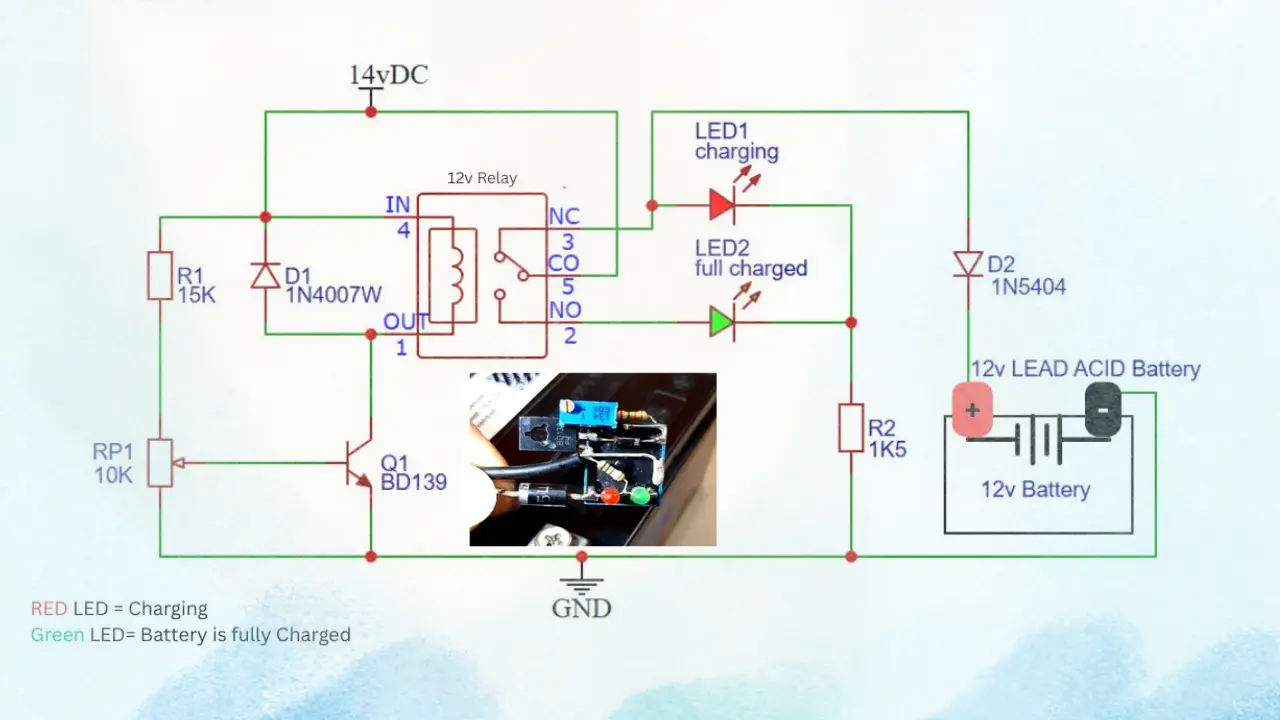
12V Automatic Battery Charger Circuit Diagram
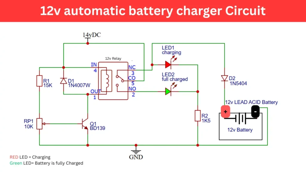
The circuit shown in fig1 uses a 14V DC power supply to charge a 12V lead acid battery. The circuit contains a relay, BD139 transistor and diode to detect voltage levels and control charging automatically. The addition of indicator LEDs makes it easy to know whether the battery is charging or fully charged.
Working Principle
The circuit is powered by a 14V DC source from a transformer. This voltage is slightly higher than the nominal 12V battery voltage. This high voltage is required proper charging. When the battery is discharged, the voltage at its terminals is low, and the transistor BD139 remains OFF.
The relay (RLY1) stays in its normally closed (NC) position, so it allowing the current to flow through diode D2 and start charging the battery. The Red LED (LED1) glows, this indicating the battery is charging.
Automatic Cut off When Fully Charged
As the battery voltage rises to its fully charged level (around 13.8–14.4V), the voltage at the base of Q1 (controlled by RP1) increases enough to switch it ON.
When transistor Q1 conducts, it turn on the relay coil and which moves the contact from NC to NO, this will disconnecting the charging supply. so the Charging stops automatically. Red LED (LED1) turns OFF and Green LED (LED2) glows, indicating that the battery is fully charged.
Recharging Cycle
Once the battery’s voltage drops below the preset level (due to usage or self-discharge), the transistor Q1 turns OFF, de energizing the relay. The contact switches back to NC, reconnecting the charger to the battery and the charging cycle begins again. this process is automatically repeats.
Applications
- Emergency lights
- UPS systems
- Solar power setups
- Automotive batteries
- Inverter battery maintenance