The Clap LED Turn ON Circuit is a simple and fun sound-activated project that turns on an LED when you clap your hands or make a sharp sound. It uses a microphone condenser, a few resistors, a capacitor, and two BC547 transistors to detect and amplify the sound signal and turn ON connected LED. This circuit is ideal for beginners who want to explore basic electronics and transistor amplification.
Components Required
- Q1, Q2 – BC547 NPN Transistors
- R1 – 1kΩ Resistor
- R2 – 2.2kΩ Resistor
- R3 – 470kΩ Resistor
- R4 – 1kΩ Resistor
- C1 – 100µF / 16V Capacitor
- MK1 – Microphone Condenser
- LED1 – Light Emitting Diode (Any Color)
- Power Supply – 6V DC
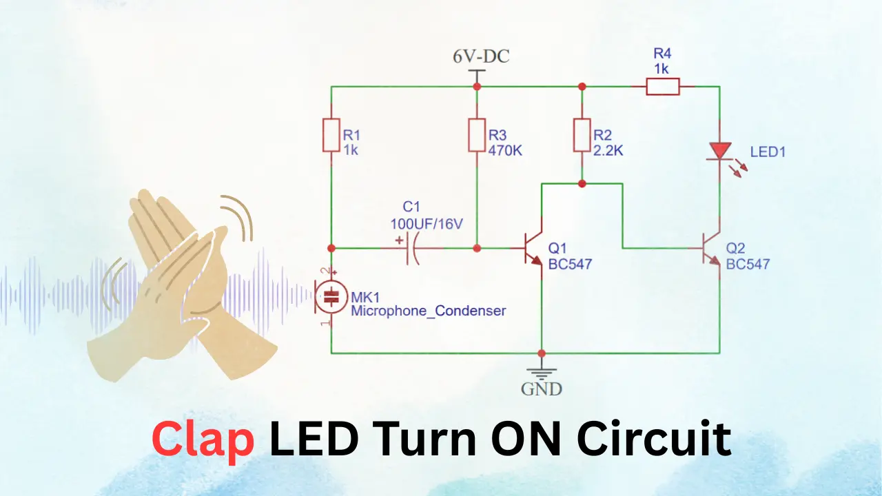
Clap LED Turn ON Circuit Diagram
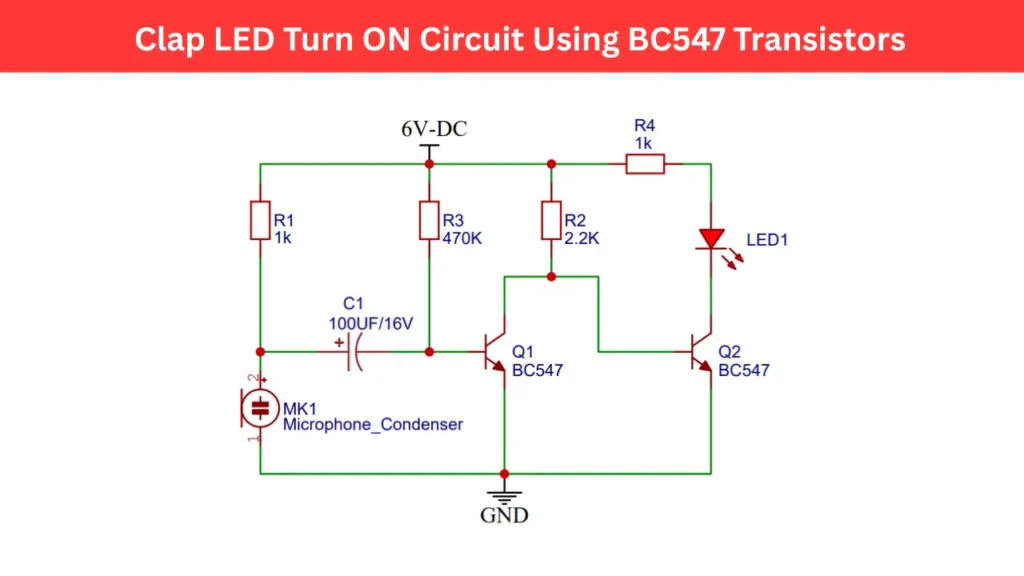
Circuit Working Principle
The working of this clap activated LED circuit is based on sound detection and signal amplification. The microphone condenser is acts as a sound sensor. When you clap, the microphone converts the sound waves into a small electrical charged signal. This weak signal is not enough to drive the LED directly. so we need a amplification stage using transistor.
The first transistor Q1 of BC547 amplifies the weak signal from the microphone. The amplified pulse from Transistor Q1 is fed to the base of transistor Q2 of BC547 through a resistor R2. When Q2 receives the signal, it switches ON the transistor and allowing current to flow through the LED and resistor R4, This will turning LED ON for some time.
Tips for Better Performance
- Use a sensitive electret microphone for better sound detection.
- Adjust R3 (470kΩ) to fine tune the circuit’s sensitivity.
- You can replace the LED with a relay driver stage to control lamps or fans.
- Power the circuit with a regulated 6V DC adapter for stable operation.