In this article I’m sharing a Smart Traffic light system using Arduino Uno and Joystick module. You can control the light based on the movements of joystick. This is a an interesting electronic project for hobby electronic enthusiast and beginners in electronics. The Connection diagram and Arduino traffic light system programming code also given below.
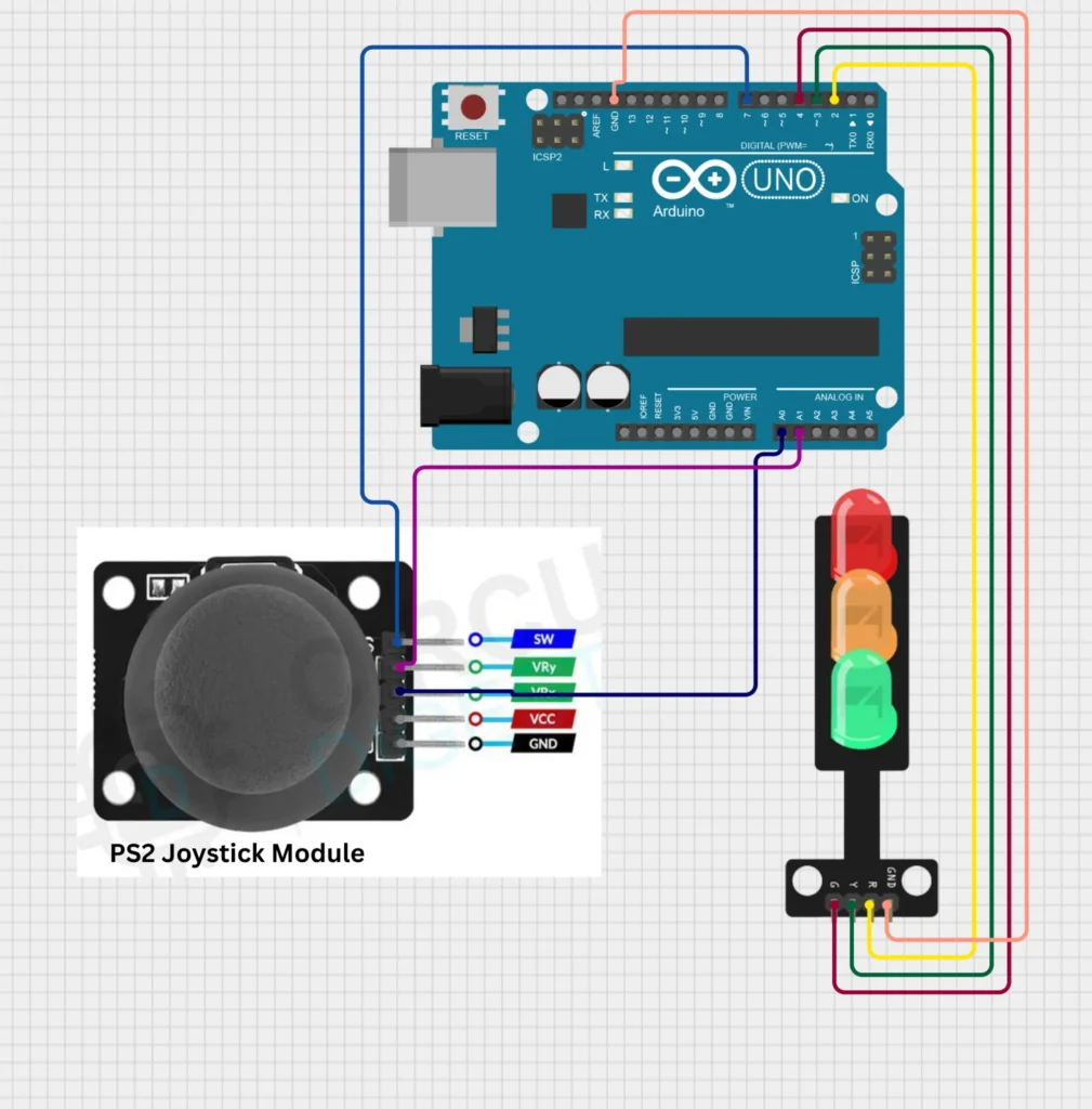
Connection Diagram
Working
When the joystick is moved up, the red LED turns on.
When the joystick is moved left, the yellow LED turns on.
When the joystick is moved right, the green LED turns on.
When the joystick is moved down, all LEDs turn on.
Connection
The Joystick module “Vry” and “Vrx” pins are connected to the Arduino analogue pins of A1 and A0. Pin “SW” is the switch pin of joystick is connected to the Pin number 7 of Arduino, but this button does not have any function here. if you want any additional option you can use it by changing the SW function in the code.
The Red LED connecting to the Arduino digital pin number 2 , Yellow LED to digital pin number 3 and Green LED to Digital pin number 4 of Arduino. Connect the VCC of joystick module to the 5V DC supply and GND connection to the common ground connection. Now the connections are completed.
Programming Code
/*
 * This Arduino sketch controls a traffic light system using a joystick module.
 * When the joystick is moved up, the red LED turns on.
 * When the joystick is moved left, the yellow LED turns on.
 * When the joystick is moved right, the green LED turns on.
 * When the joystick is moved down, all LEDs turn on.
 */

// Pin definitions
const int VRX_PIN = A0; // Joystick X-axis
const int VRY_PIN = A1; // Joystick Y-axis
const int SW_PIN = 7;   // Joystick button (not used)
const int RED_LED_PIN = 2;   // Red LED
const int YELLOW_LED_PIN = 3; // Yellow LED
const int GREEN_LED_PIN = 4;  // Green LED

void setup() {
  // Initialize serial communication
  Serial.begin(9600);

  // Set LED pins as outputs
  pinMode(RED_LED_PIN, OUTPUT);
  pinMode(YELLOW_LED_PIN, OUTPUT);
  pinMode(GREEN_LED_PIN, OUTPUT);

  // Set joystick button pin as input
  pinMode(SW_PIN, INPUT);
}

void loop() {
  // Read joystick values
  int xValue = analogRead(VRX_PIN);
  int yValue = analogRead(VRY_PIN);

  // Determine joystick direction
  if (yValue < 300) { // Joystick moved up
    digitalWrite(RED_LED_PIN, HIGH);
    digitalWrite(YELLOW_LED_PIN, LOW);
    digitalWrite(GREEN_LED_PIN, LOW);
  } else if (xValue < 300) { // Joystick moved left
    digitalWrite(RED_LED_PIN, LOW);
    digitalWrite(YELLOW_LED_PIN, HIGH);
    digitalWrite(GREEN_LED_PIN, LOW);
  } else if (xValue > 700) { // Joystick moved right
    digitalWrite(RED_LED_PIN, LOW);
    digitalWrite(YELLOW_LED_PIN, LOW);
    digitalWrite(GREEN_LED_PIN, HIGH);
  } else if (yValue > 700) { // Joystick moved down
    digitalWrite(RED_LED_PIN, HIGH);
    digitalWrite(YELLOW_LED_PIN, HIGH);
    digitalWrite(GREEN_LED_PIN, HIGH);
  } else { // Joystick in neutral position
    digitalWrite(RED_LED_PIN, LOW);
    digitalWrite(YELLOW_LED_PIN, LOW);
    digitalWrite(GREEN_LED_PIN, LOW);
  }

  // Small delay to stabilize readings
  delay(100);
}
Akhil Satheesh is an electronics expert and the Founder and CEO of Soldering Mind. Specializes in designing innovative electronic circuits and custom, high-performance PCB layouts. Every project he shares on solderingmind.com is rigorously bench-tested to ensure accuracy for makers and hobbyists alike.