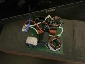
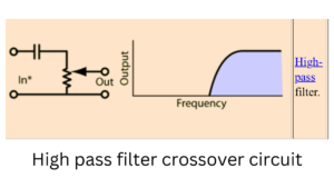
Improve your speaker’s high frequency performance with a tweeter crossover circuit. This circuit will gives a clear, distortion free treble by directing the right frequencies to your tweeter. So in this article sharing the information’s such as Tweeter crossover circuit and its working explanations along with list of components required to build this.
Components Required
- 1 × Capacitor – 4.42 µF (Non-polarized / Bipolar Electrolytic or Film Type)
- 1 × Resistor – 10Ω, 10W (Wire-wound or Power Resistor)
- 1 × Tweeter Speaker
- Wires for connections
- Soldering tools (soldering iron, solder wire)
- Heat shrink tubing or electrical tape (for insulation)
- Optional: Small PCB or breadboard (for mounting components).
Tweeter Crossover Circuit diagram
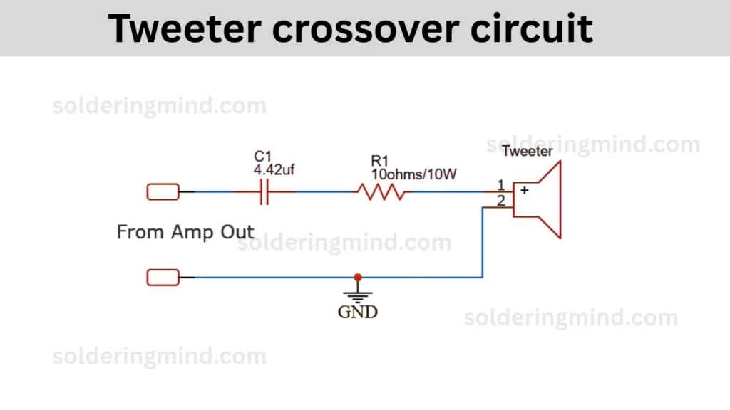
This tweeter crossover circuit is designed to allow only the high frequency audio signals to reach the tweeter speaker and also blocking the low frequencies that could damage it or cause distortion.
How the Circuit Works
The audio signal from the amplifier goes through the input section and The capacitor C1, which will removes the bass and midrange frequencies. The resistor R1, will reduces the power to a safe level for tweeter. The tweeter receives only high frequencies with controlled power.
Cutoff Frequency Calculation
The cut off frequency of the circuit is calculated using the formula of,
Fc = 1/2πRC
- Where FC is cutoff frequency
- R is resistance in ohms
- C is capacitance value in farad.
- R=10Ω
- 𝐶 = 4.42𝜇𝐹 = 4.42×10⁶𝐹
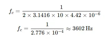
The tweeter crossover point is approximately 3.6 kHz. Perfectly suitable for most of the tweeters.