
Most audio enthusiasts use an Audio crossover circuit to get smooth sounds from the audio amplifier. yes, the crossover circuit can able to separate the High, Mid, and low frequencies. The crossover circuits are available in two types. The Passive audio-crossover and the other is the Active audio-crossover circuit. So in this article, I’m going to explain how to build a Passive audio-crossover circuit (2-way crossover circuit ).

This 2-way crossover circuit is designed for the center channel speaker of your home audio amplifiers. if you are building 5.1 audio amplifiers it will help you to isolate the center channel audio frequency. The circuit diagram is separated by 2 sections which means 2way.
Passive Audio crossover circuit diagram
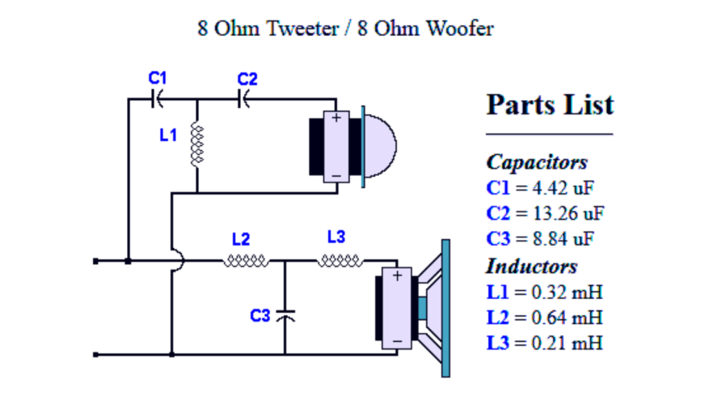
The first one is the high-pass section. This section will pass high-frequency audio signals to the tweeter. The frequencies range from about 3000 Hz to 20 kHz.
The second section is mid-range, which means mid-frequency, not high-frequency or low-frequency. This is called a band-pass filter. Most of the cinematic or human vocal sounds are in this frequency range.
The L1, C1, and C2 will pass frequencies between 2 Hz and 20 Hz, which is suitable for the tweeter speakers. The L2, L3, and C3 will pass frequencies between 200 Hz and 4 Hz.
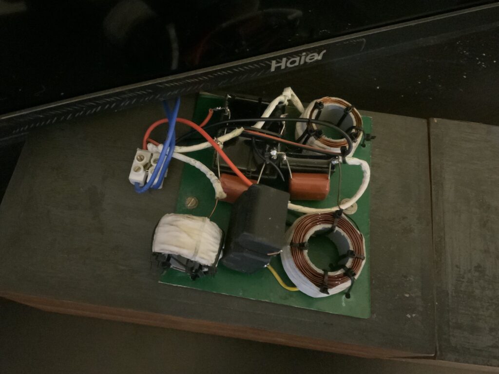
Assembled passive audio crossover setup

Crossover looks good. One question, the two speakers are 8 ohms. With the crossover will the output still be 8ohms.