If you are interested in making an inverter circuit, This could be very fantastic circuit for hobby electronics lovers. so the simple circuit will work with a few components. A PWM ic of SG3525 has to be implemented as the master is to operate in this circuit.
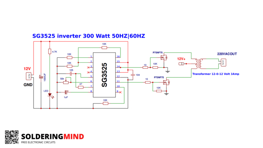
300watt SG3525 Inverter Circuit Diagram With Free PCB Layout
The mini inverter can be used as a small ups for your wireless router, Mobile phone charger, and also any small electronic appliances. The complete circuit works in 12V DC input. A medium type of battery is good for the circuit.
Inverter Circuit Diagram
Components List
| Components Name | Quantity |
| SG3525 IC | 1 |
| 1000UF/25V CAPACITOR | 1 |
| LED | 1 |
| 4.7K RESISTOR | 1 |
| 10K RESISTOR | 6 |
| 105PF DISC CAPACITOR | 1 |
| 50K POT | 1 |
| P75N75 MOSFET | 2 |
| 47 OHMS RESISTOR | 1 |
| 104 PF DISC CAPACITOR | 1 |
| 10 OHMS RESISTOR | 2 |
| 12-0-12 3A STEP DOWN TRANSFORMER | 1 |
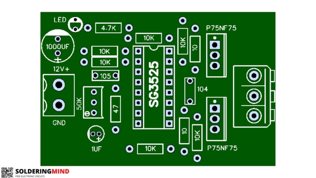
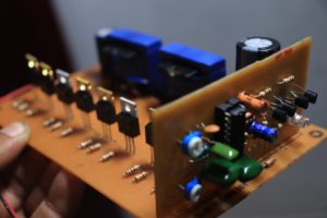
PCB Layout

Bu devreyi yaptım fakat 12v DC verince kesip kesip duruyor
Hi, where can i insert a pot, and /or resistors to vary the duty cycle a bit,say, down to 40 or 45%?