In this article I’m sharing level indicator for water tank based circuit project. The circuit diagram and working principle explained here. This circuit is working based on A1015 PNP transistor and 3 indication LED’s. This circuit is simple and easy to build.
Circuit Diagram
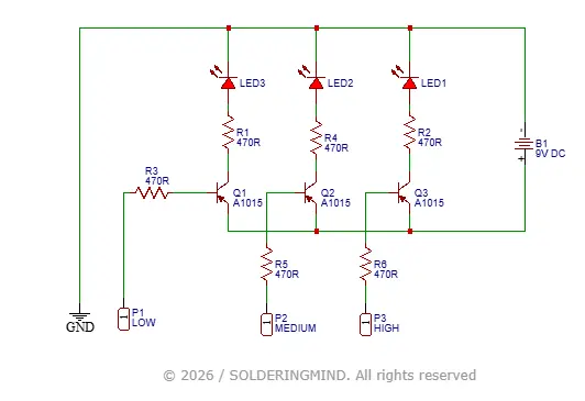
The circuit is designed with three A1015 PNP transistors. Each transistors are connected to their corresponding LED. The three LED indicating Low, Medium and High water Level indications.
Components Required
| Component | Value / Part | Quantity | Notes |
|---|---|---|---|
| LED | Standard LED (any color) | 3 | Labeled LED1, LED2, LED3 |
| Resistor | 470 Ω | 6 | R1, R2, R3, R4, R5, R6 |
| Transistor | A1015 (PNP) | 3 | Q1, Q2, Q3 |
| Battery | 9V | 1 | B1 |
| Input Terminal | input goes to water tank | 3 | P1 (LOW), P2 (MEDIUM), P3 (HIGH) |
| Ground | — | 1 | Common ground reference |
| Connecting Wires | — | As needed | For circuit connections |
Circuit Connection
The three A1015 transistor represents the level detection of water in water tank. The P1, P2 and P3 represents the connections goes to the water tank for level detection.
P1 goes to the bottom of water tank, which indicates the low level of water in water tank. P2 placing in the middle of the tank, it indicated the tank has half of water in it. The last is P3 at the top to indicates Tank full indication.
The each LED is connected with a 470ohms resistor to limit the current and protect the LED from over voltage. The Base is connected with a 470 ohms resistor and goes to the probes connections.
This entire circuit is working on a 9V DC supply, you can use a(V battery to powering the circuit. other way is connect the circuit to a DC adapter.
Working Principle
This circuit is working based on conduction of charge through water and make the circuit complete. The transistors base pin is connected to the water level for detection.
If the ground connection and base pin is connected via the water the LED will turn ON. This technique is used in water level indicator circuit. The placed probes re in different area of the water tank, when the water reaches to the probes and lights glow when circuit get complete.
Water Level Indicator with Alarm on Tank Full with 5 Sensors
- Automatic Water Level Indicator With Overflow Buzzer Sound. With Stop Buzzer Push Button. and 5 Sensor. Four Level water Indication 25%, 50% ,75%, 100%, ,Micro Controller Based Design ,Buzzer off Button For Sound Off Buzzer .
As an Amazon Associate, I earn from qualifying purchases.
🔥 Check Price on Amazon