Hi friends, the S8050 transistor name is familiar from the old days, but J3Y is new to you. The J3Y is an NPN SMD transistor which is commonly used in iPhone motherboards and Android smartphones. J3Y is the marking code for S8050 SMD variant transistor. In this article, I am sharing the J3Y Transistor pinout, equivalent transistors for replacement, and its specifications as well.
What is the J3Y (S8050) Transistor?
J3Y is the official marking code for the SMD variant of the S8050 NPN transistor. This BJT transistor is used for low voltage, high current, and small signal amplification purposes. This tiny component can handle 25V collector to emitter voltage and 500mA of current.
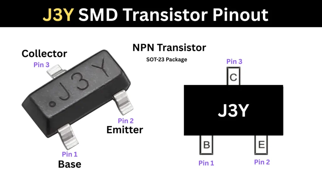
J3Y Transistor Pinout Diagram
Pin Configuration
To check the pinout configuration of the transistor, you need to place the transistor on a flat surface with the single pin pointing up and the other two pins at the bottom. The two bottom pins, the left pin is the Base, the one next to it is the Emitter, and the top pin is the Collector, as shown in the table below.
| Pin Number | Pin Name |
|---|---|
| 1 | Base (B) |
| 2 | Emitter (E) |
| 3 | Collector (C) |
Technical Specifications
- Type: SMD NPN Transistor
- Packaging is SOT-23
- Collector-Base Voltage is 40V
- Collector-Emitter Voltage is 25V
- Emitter-Base Voltage is 5V
- Continuous Collector Current is 500mA
- Power Dissipation is around 300mW
Complementary Transistor of J3Y
The complementary transistor of J3Y (NPN Transistor) is Transistor marked in label of 2TY (PNP Transistor).
Equivalent Transistors for Replacement
- You can use MMBT8050 or MMBT8050LT1G These are the standard SMD equivalents from manufacturers like ON Semi and Diodes Inc.
- The BC817 Transistor is a common NPN SOT-23 transistor it can also similar specifications of 500mA and 45V.
How to Test a J3Y (S8050) Transistor Using a Multimeter
How to Test J3Y SOT-23 using multimeter
- Multimeter settings change
Turn the rotary dial to the Diode Test mode
- Understand the transistor type and current flow direction
In NPN transistor, the current will only flow from the Base to the Collector or Emitter.
- Test Base to Emitter (B to E)
Connect multimeter Red Probe to the Base (Left Pin) and the Black Probe to the Emitter. if it is good condition reading shows the voltage drop between 0.45V and 0.9V
- Test Base to Collector (B to C)
Connect the Red probe to the base and black probe to the collector. If it shows the 0.45v to 09V means it is working good.
- Probe swapped with the pins checks
The Red probe is connected either collector or emitter and the black probe in base pin show Open loop means the transistor is good.
Applications
- This SOT-23 NPN transistor is commonly using in low power, low voltage and small signal amplification circuits.
- Used Relay solenoid drivers.
- Smartphone circuits.
- DC to DC converter and other portable electronic devices.